Electronic circuit
a technology of electronic circuits and circuits, applied in the direction of power reduction by adiabatic operation, power consumption reduction, pulse technique, etc., can solve problems such as performance degradation of electronic circuits, and achieve the effect of low electrical power voltage and high performan
- Summary
- Abstract
- Description
- Claims
- Application Information
AI Technical Summary
Benefits of technology
Problems solved by technology
Method used
Image
Examples
first embodiment
[0031]FIG. 3A illustrates a circuit diagram of an electronic circuit in accordance with a first embodiment. FIG. 3B illustrates a circuit diagram of an electronic circuit in galvanically. In an electronic circuit 50, a distributed parameter line L4, a capacitor C5 and a distributed parameter line L6 are coupled to in series between the drain D2 of the second transistor T2 and the gate G3 of the transistor T3. The node N2 between the distributed parameter line L4 and the capacitor C5 is grounded via the distributed parameter line L7 and the capacitor C4. The direct voltage VDD is applied to a node between the distributed parameter line L7 and the capacitor C4 for cutting direct current via a choke inductor such as a stab. The distributed parameter line L3 and the second resistor R2 are coupled in series between the node N1 and the source S3. A distributed parameter line L8 is coupled between the third node N3 between the distributed parameter line L3 and the second resistor R2 and a ...
second embodiment
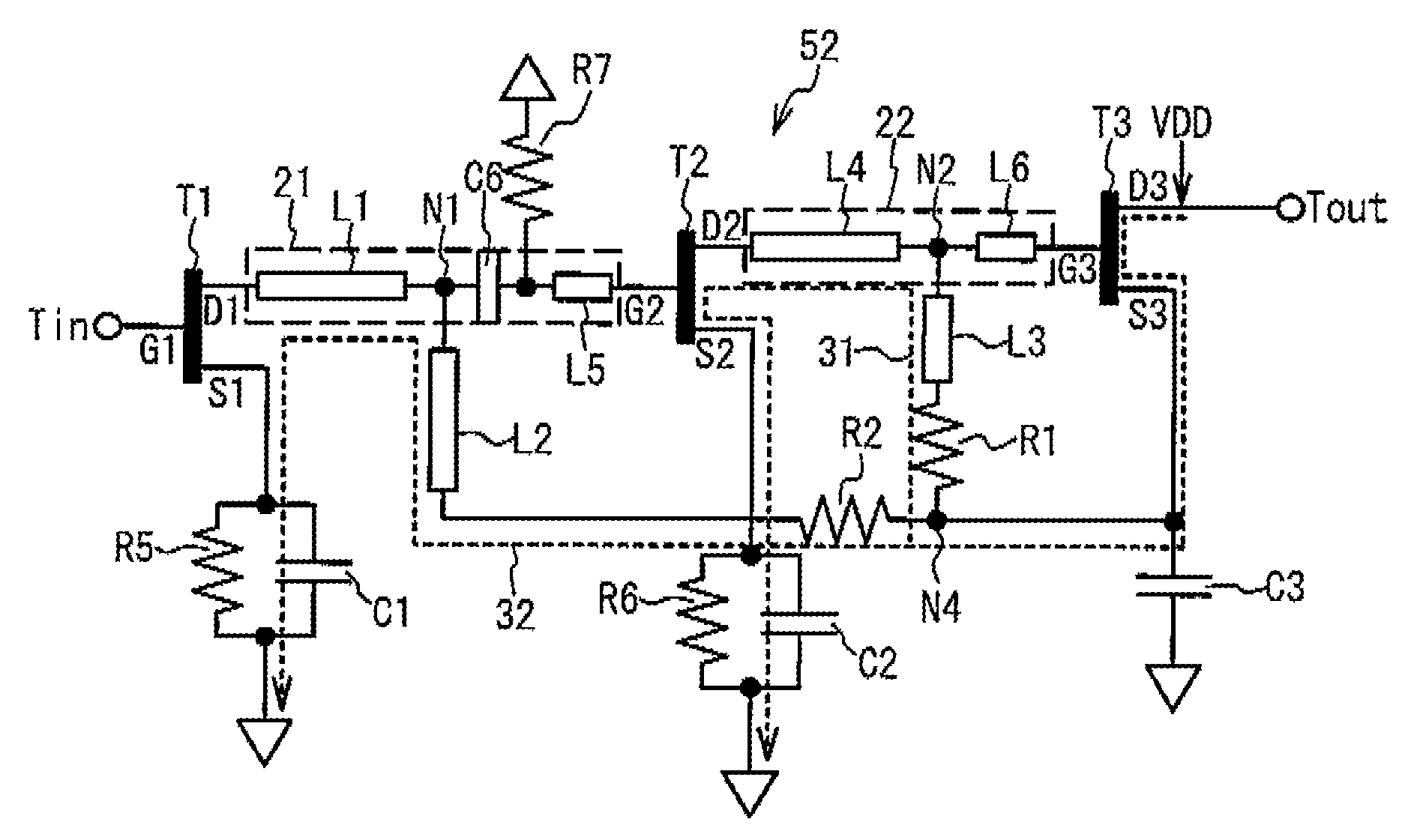
[0051]FIG. 5A illustrates a circuit diagram of an electronic circuit in accordance with a second embodiment. FIG. 5B illustrates a circuit diagram of the electronic circuit in galvanically. In an electronic circuit 52, the distributed parameter line L1, the capacitor C6 and the distributed parameter line L5 are coupled in series between the drain D1 of the first transistor T1 and the gate G2 of the second transistor T2. A node between the capacitor C6 and the distributed parameter line L5 is grounded via the resistor R7. The distributed parameter line L3 is coupled between the node N4 between the distributed parameter line L2 and the first resistor R1 and the node N2 between the distributed parameter line L4 and the distributed parameter line L6. In FIG. 5B, the resistor R7 is grounded in galvanically. The distributed parameter lines L1, L2 and L5 and the capacitor C6 make impedance matching between the first transistor T1 and the second transistor T2. The capacitor C6 transmits a h...
PUM
 Abstract
Description
Claims
Application Information
 - R&D
- Intellectual Property
- Life Sciences
- Materials
- Tech Scout
- Unparalleled Data Quality
- Higher Quality Content
- 60% Fewer Hallucinations
Browse by: Latest US Patents, China's latest patents, Technical Efficacy Thesaurus, Application Domain, Technology Topic, Popular Technical Reports.
© 2025 PatSnap. All rights reserved.Legal|Privacy policy|Modern Slavery Act Transparency Statement|Sitemap|About US| Contact US: help@patsnap.com


