Antireflection film, display device and light transmissive member

a technology of anti-reflection film and display device, which is applied in the direction of optical elements, identification means, instruments, etc., can solve the problems of surface and reflection on the interface between film surface and display surface that are typically deviating from ideal conditions, and the display is extremely difficult to s

Active Publication Date: 2012-03-22
SHARP KK
View PDF3 Cites 24 Cited by
  • Summary
  • Abstract
  • Description
  • Claims
  • Application Information

AI Technical Summary

Benefits of technology

[0038]With the antireflection film according to the present invention, scattering of light incident on the antireflection film can be suppressed such that cloudiness is less likely to occur on a display when the antireflection film is disposed on a surface of a display device or an optical member.

Problems solved by technology

However, reflection on an interface between air and the film surface and reflection on an interface between the film surface and the display surface typically deviate from ideal conditions in terms of respective amplitude reflectance values and phase values thereof.
Hence, reflected light resulting from the reflection is not cancelled out completely, and as a result, a sufficient antireflection effect is not realized.
Therefore, with LR treatment alone, peripheral light is reflected at a constant reflectance so that images from a light source such as a fluorescent lamp are reflected on a display, making the display extremely difficult to see.

Method used


Image

  • Antireflection film, display device and light transmissive member
  • Antireflection film, display device and light transmissive member
  • Antireflection film, display device and light transmissive member

Examples


first embodiment

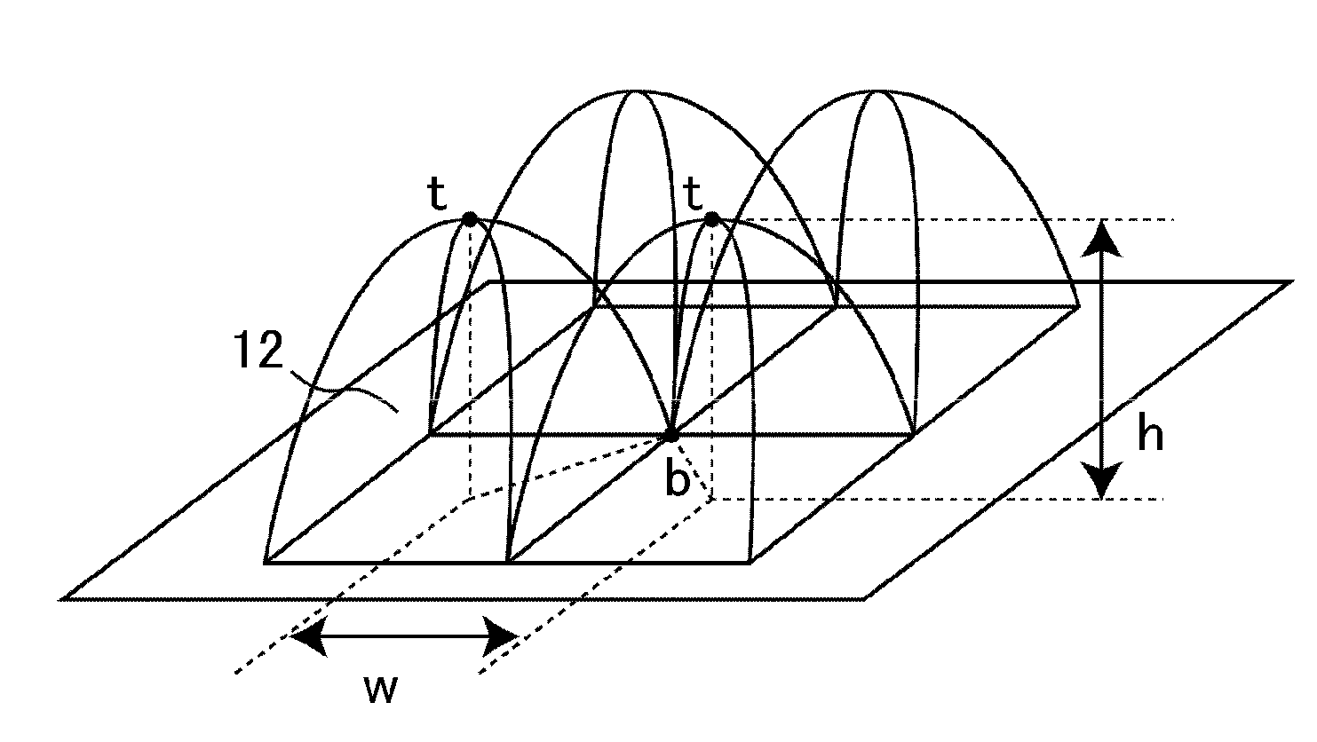
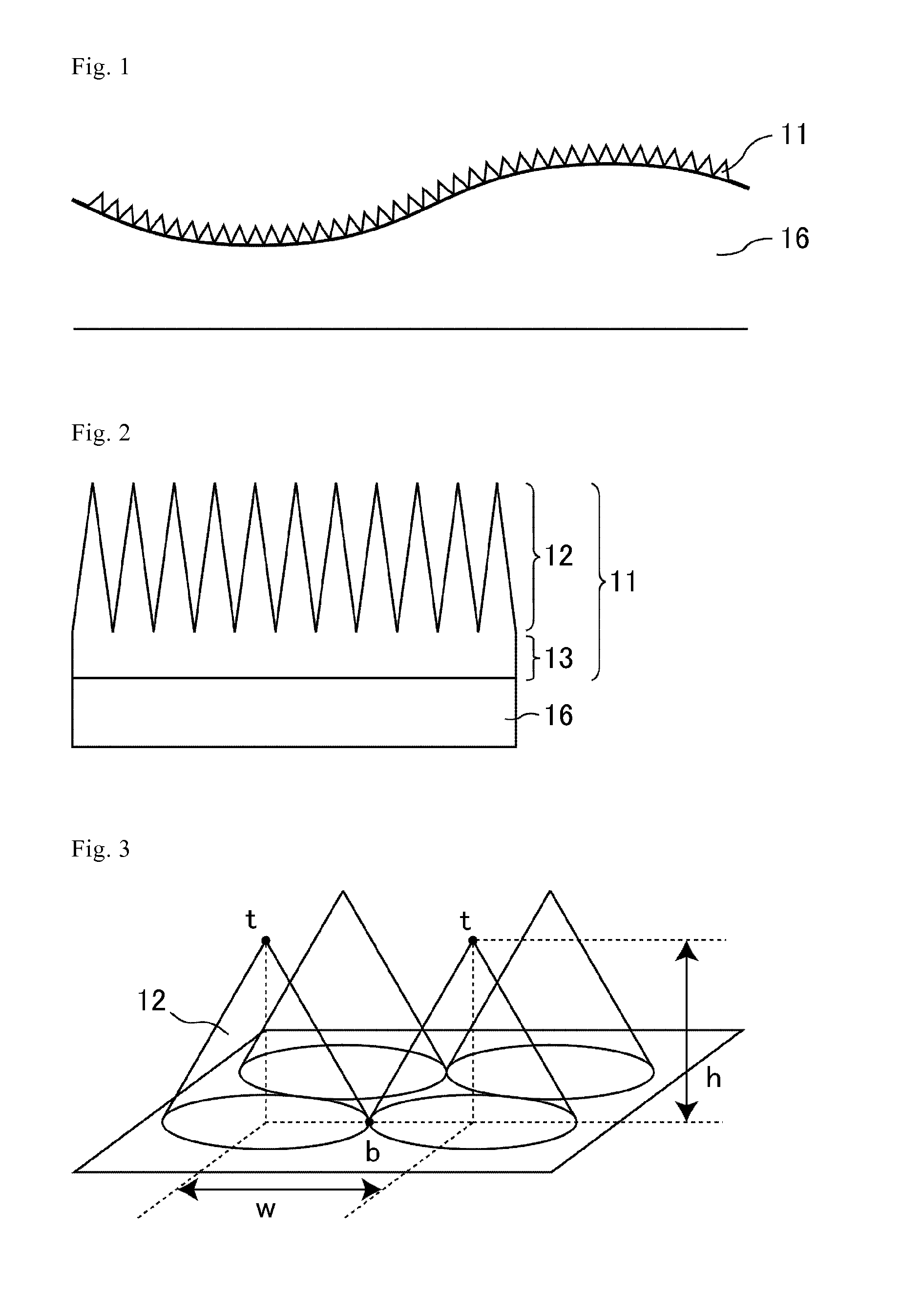
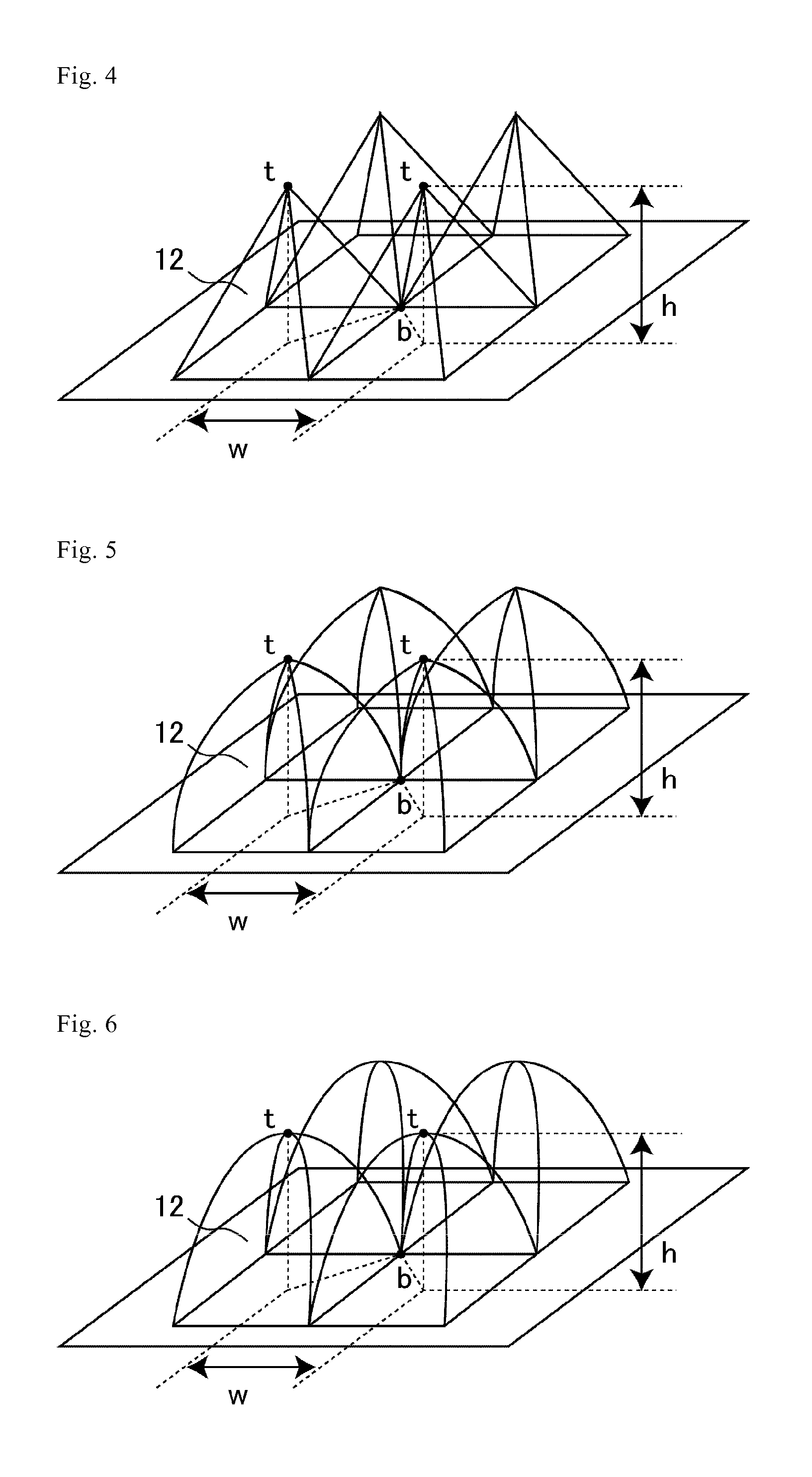
[0109]FIGS. 1 and 2 are sectional schematic views showing a moth-eye film (antireflection film) according to a first embodiment. FIG. 1 shows the entire moth-eye film, and FIG. 2 shows an enlargement of convex portions. As shown in FIGS. 1 and 2, a moth-eye film 11 according to the first embodiment is provided on a base 16 which is the target of an antireflection treatment. There are no particular limitations on the material of the base 16 as long as respective antireflection films can be carried thereon. The base 16 may be either translucent or opaque. In the case that the base is an opaque base, a reflection prevention effect on the surface of the opaque base is realized. For example, in the case of a black base, a jet, black appearance is obtained, and in the case of a colored base, an appearance having a high purity of color is obtained. Thus, a product having a superior design property is obtained. There are no particular limitations on the shape of the base 16, and, for exampl...


PUM

PropertyMeasurementUnit
Temperatureaaaaaaaaaa

Abstract

An antireflection film is provided in which a light scattering property is suppressed. In at least one example embodiment, the antireflection film includes, on a surface thereof, a moth-eye structure including a plurality of convex portions such that a width between vertices of adjacent convex portions is no greater than a wavelength of visible light. In at least one example embodiment of this antireflection film, the moth-eye structure does not include a sticking structure formed when tip end portions of the convex portions are joined to each other.

Description

TECHNICAL FIELD[0001]The present invention relates to an antireflection film, a display device, and a light transmissive member. More specifically, the present invention relates to an antireflection film provided for use on a surface of a base, a display device including the antireflection film, and a light transmissive member including the antireflection film.BACKGROUND ART[0002]Various functions, such as an anti-scratch function, a function for preventing external light reflection, and an anti-soiling function, are required on a surface of a display such as a CRT (Cathode Ray Tube) display, an LCD (Liquid Crystal Display), a PDP (Plasma Display Panel), and an EL (Electroluminescence) display.[0003]In an example of a method for providing a function for preventing external light reflection, LR (Low Reflection) treatment is implemented by providing a material having a different refractive index to that of a material constituting the display as a film on a surface of the display such ...

Claims


Application Information

Patent Timeline
IPC IPC(8): G02B1/11B82Y30/00G02B1/118G02F1/1335G09F9/00H01J5/16
CPCG02F1/133502G02B1/118
Inventor TAGUCHI, TOKIOIMAOKU, TAKAO
Owner SHARP KK
Why Eureka
Try Eureka