
Craft and method for assembling craft with controlled spin

a technology of controlled spin and assembling method, which is applied in the field of craft, can solve the problems that the fan turning also produces an unwanted canopy turning, and achieves the effect of reducing the number of parts and reducing the cost of production

Active Publication Date: 2012-03-22
AESIR
View PDF11 Cites 14 Cited by
  • Summary
  • Abstract
  • Description
  • Claims
  • Application Information

AI Technical Summary

Benefits of technology

[0009]It has also been found that locating the vanes upstream allows control of turning effects to be achieved using smaller vane movement than required when the vane is located downstream on the lift generating surface.
[0010]A balance needs to be made between a large number of aerofoil control vanes (to maximise their effectiveness in diverting the airflow towards the radial direction) and a small number (to minimize drag). There may be some situations where it is best to have a relatively small number of vanes shaped to divert the flow to and beyond the radial in order to compensate for their reduced number.

Problems solved by technology

It is known, eg from U.S. Pat. No. 5,203,521 that, in vehicles of this type, the turning of the fan also tends to produce an unwanted turning of the canopy.

Method used


Image

  • Craft and method for assembling craft with controlled spin
  • Craft and method for assembling craft with controlled spin
  • Craft and method for assembling craft with controlled spin

Examples


Embodiment Construction

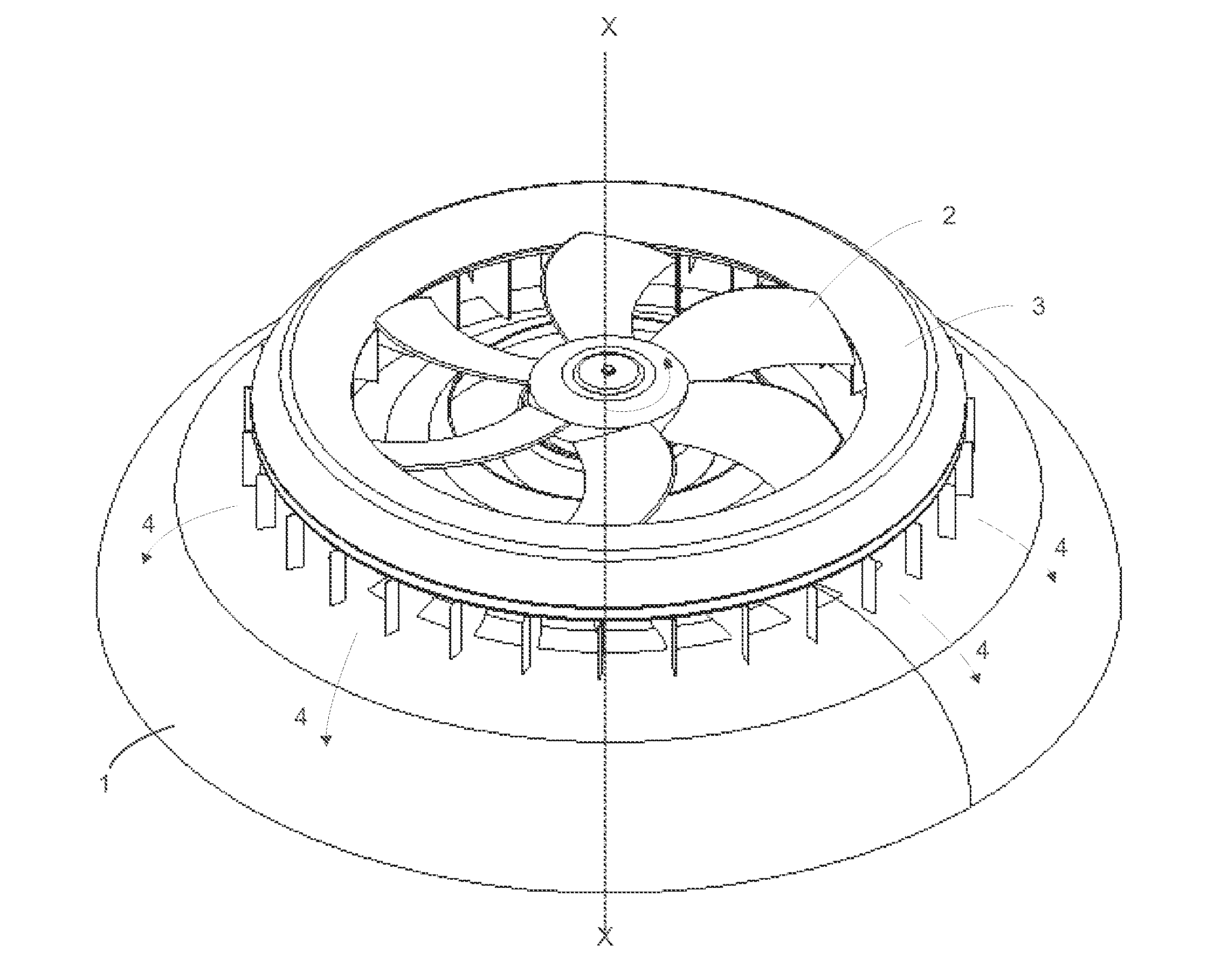
[0024]Referring to the figures there is shown a vertical take off aircraft having a canopy 1 defining an aerodynamic surface of double convex curvature and an axial fan 2, which, in this particular example, is driven anticlockwise as seen in FIG. 1. The fan 2 is driven by an engine or motor, not illustrated, housed within the canopy 1.

[0025]A shroud 3 is supported above the canopy and extends circumferentially around the fan 2 such as to define a duct within which the fan 2 is housed.

[0026]Air is drawn into the fan 2 from above the canopy along the axis as indicated by line X-X and is expelled as a jet over the curved surface of the canopy as indicated by arrows 4. By virtue of the Coanda effect the jet follows the curve of canopy 1, diverted from a plane of the fan normal to the axis X-X, towards the axial direction; and the jet finally parts from the canopy surface at its lower edge 5. This diversion of the jet towards the vertical axis generates vertical lift.

[0027]Because of the...


PUM

PropertyMeasurementUnit
swirl angleaaaaaaaaaa

Abstract

This invention relates to a craft designed to move through or on a surface of a fluid. It is believed to be principally of use in relation to airborne craft and missiles but the theory behind the invention is equally applicable for example to submarines.

Description

FIELD OF THE INVENTION[0001]This invention relates to a craft designed to move through or on a surface of a fluid. It is believed to be principally of use in relation to airborne craft and missiles but the theory behind the invention is equally applicable for example to submarines.BACKGROUND OF THE INVENTION[0002]The invention arose in the design of a craft of the type in which a fan is used to direct a radial jet of air over a curved canopy. The canopy is shaped so as to divert the flow of air from a radial to an axial direction to produce lift. This invention deals with the problem of increasing lift.[0003]It is known, eg from U.S. Pat. No. 5,203,521 that, in vehicles of this type, the turning of the fan also tends to produce an unwanted turning of the canopy. U.S. Pat. No. 5,203,521 relates to an aircraft having an upper deflector which deflects air from a fan onto an annular body. The deflector is supported onto the annular body by spacers or struts which form spoilers designed ...

Claims


Application Information

Patent Timeline
Patent Type & Authority Applications(United States)
IPC IPC(8): B64C39/00B23P11/00
CPCB63C11/42B63G8/16Y10T29/49826B64C39/064B63H2011/002B64C29/00B64C39/001F15D1/00
Inventor BABINSKY, HOLGERMCINTOSH, SIMONWHITCHER, LEEPOTTER, STEVE
Owner AESIR
Learn More