
Wireless sensor for an aircraft propulsion system

a propulsion system and wireless technology, applied in the direction of registering/indicating, machines/engines, registering/indicating vehicles, etc., can solve the problem that the hollow blades are also more prone to damag

Inactive Publication Date: 2012-03-22
RAYTHEON TECH CORP
View PDF7 Cites 28 Cited by
  • Summary
  • Abstract
  • Description
  • Claims
  • Application Information

AI Technical Summary

Benefits of technology

[0010]The foregoing features and the operation of the invention will become more apparent in light of the following description and the accompanying drawings.

Problems solved by technology

Disadvantageously, however, hollow blades may also be more prone to damage.

Method used


Image

  • Wireless sensor for an aircraft propulsion system
  • Wireless sensor for an aircraft propulsion system
  • Wireless sensor for an aircraft propulsion system

Examples


Embodiment Construction

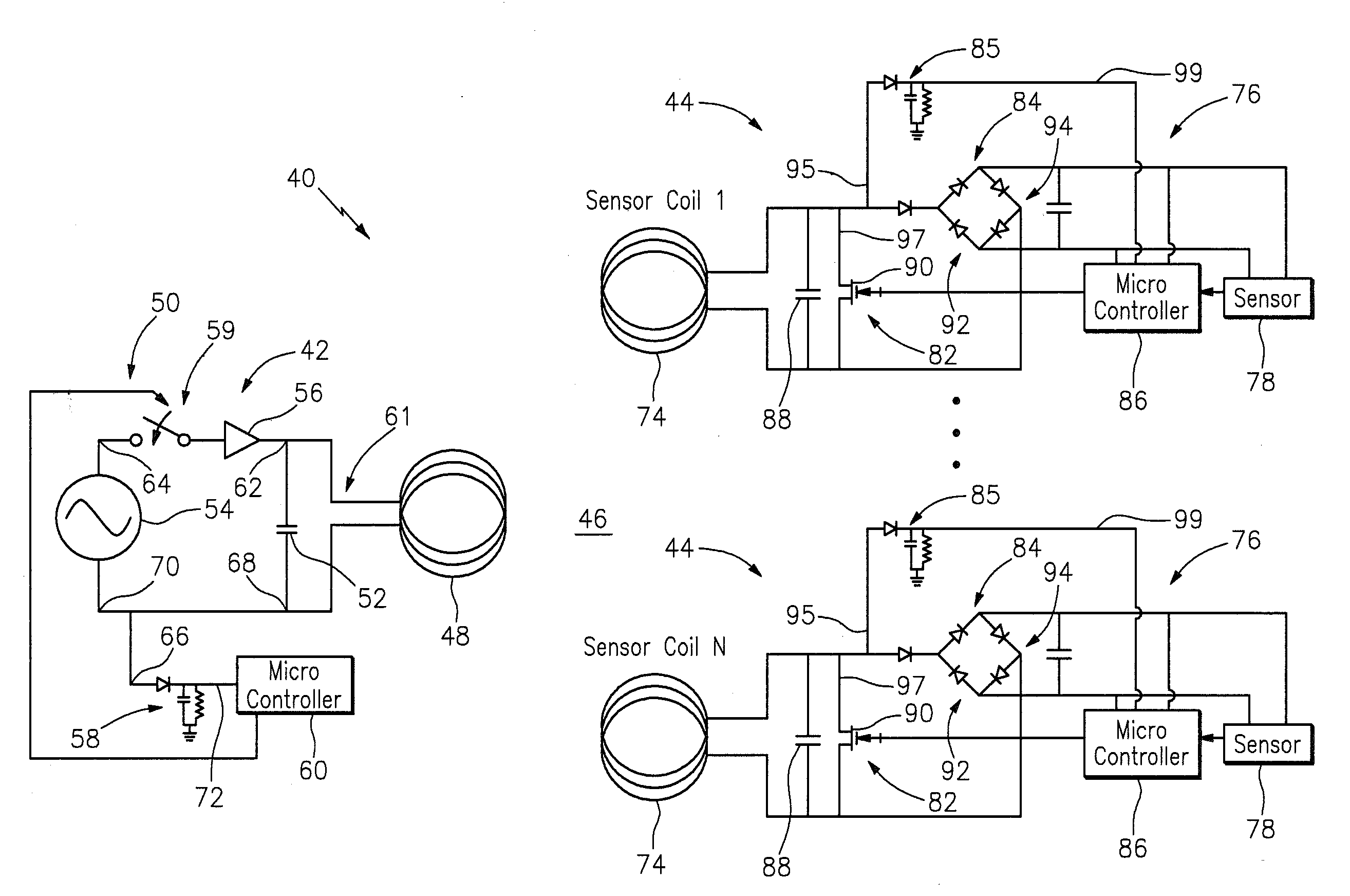
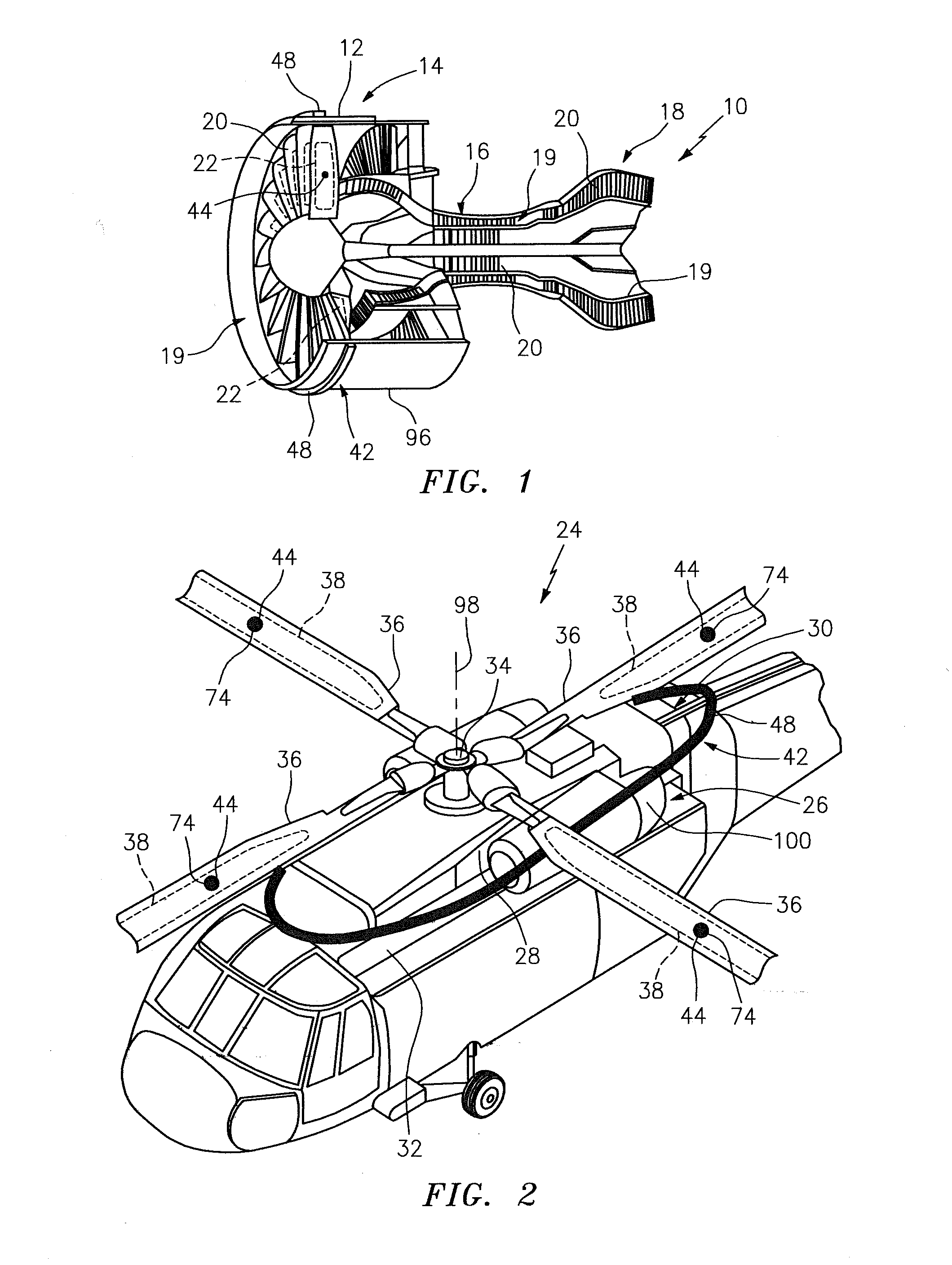
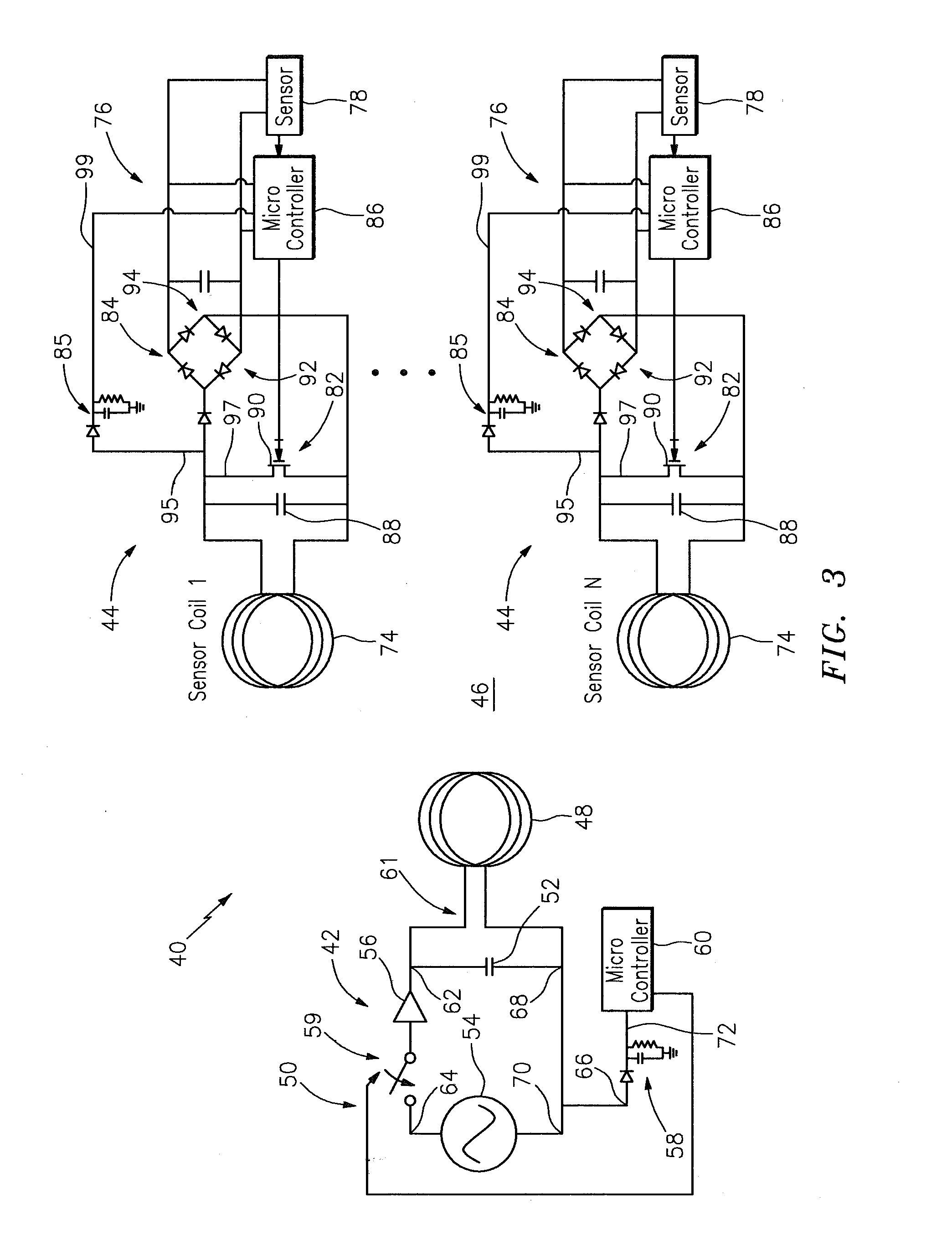
[0015]The present invention includes a method and system for wirelessly monitoring an aircraft propulsion system. At least one component of the aircraft propulsion system can be monitored, for example, by configuring a wireless monitoring system, having a primary transducer and at least one secondary transducer, with the aircraft propulsion system. The secondary transducer is wirelessly powered by a magnetic field generated by the primary transducer. A sensor, included in the secondary transducer, monitors at least one operational parameter of the aircraft propulsion system component. The secondary transducer wirelessly transmits an output signal, indicative of the monitored parameter, to the primary transducer through the magnetic field. The primary transducer can then generate sensor data from the received output signal for use in high-level control. Examples of each system and component used in this method will be described below in further detail.

[0016]Referring to FIGS. 1 and 2...


PUM


Abstract

A method is provided for wirelessly monitoring an aircraft propulsion system having a plurality of rotor blades, at least some of which rotor blades have an internal compartment. The method includes: providing a primary transducer having a primary coil, and one or more secondary transducers, each secondary transducer having a secondary coil connected to a sensor, wherein the secondary transducers are respectively disposed within the internal compartments; wirelessly powering the secondary transducers using a magnetic field generated by the primary transducer; monitoring at least one operational parameter from within each internal compartment using a respective sensor; and transmitting output signals from the secondary transducers to the primary transducer through the magnetic field, wherein the output signals are indicative of the monitored parameters.

Description

BACKGROUND OF THE INVENTION[0001]1. Technical Field[0002]This disclosure relates generally to a system and method for wirelessly monitoring an aircraft propulsion system.[0003]2. Background Information[0004]A typical aircraft propulsion system includes multiple complex components and systems. To facilitate optimal operation of such a propulsion system, sensors are used to monitor various engine parameters. Data associated with these parameters can be processed in order to maximize engine performance, increase fuel efficiency, reduce engine degradation and / or schedule engine maintenance.[0005]Recent advances in material technologies have enabled the manufacture of complex hollow blades for various aircraft propulsion systems. A typical hollow blade includes one or more sealed internal compartments. Each sealed compartment is typically evacuated, or filled with inert gas. Such hollow blades can increase engine performance and efficiency by, for example, reducing engine weight. Disadva...

Claims


Application Information

Patent Timeline
Patent Type & Authority Applications(United States)
IPC IPC(8): B64C27/00G06F19/00F01D25/00
CPCB64C27/008F05D2260/80F01D21/003B64D2045/0085
Inventor BAJEKAL, SANJAYSMITH, PETER G.LAKAMRAJU, VIJAYA RAMARAJUSOLDNER, NICHOLAS CHARLES
Owner RAYTHEON TECH CORP
Learn More