Rotating disk lock mechanism

a technology of rotating disks and locking mechanisms, which is applied in padlocks, building locks, constructions, etc., can solve the problems of limited capacity, limited potential combinations, and length of portions, and achieve enhanced potential combinations, enhanced potential combinations, and enhanced potential combinations

Active Publication Date: 2012-03-22
INNER TITE A DIV OF YARA ENG
View PDF12 Cites 5 Cited by
  • Summary
  • Abstract
  • Description
  • Claims
  • Application Information

AI Technical Summary

Benefits of technology

[0009]It is an additional object of the present invention to provide a rotating disk lock mechanism that provides an enhanced number of potential combinations.
[0010]It is an additional object of the present invention to provide a rotating disk lock mechanism that provides an enhanced number of potential combinations without increasing the number of rotating disks or the dimensions of the lock.
[0011]It is an additional object of the present invention to provide a rotating disk lock mechanism that provides an enhanced number of potential combinations through the use of rotating disks and keys that include mating surfaces of a reduced size.
[0012]It is an additional object of the present invention to provide a rotating disk lock mechanism that provides an enhanced number of potential combinations through the use of rotating disks and keys that include mating surfaces of a reduced size.

Problems solved by technology

The universe of potential combinations is limited, however, in that conventional barrel locks can only accommodate six rotating combination disks.
This restricted capacity is the result of industry standards that limit the length of the portion of the barrel lock in which the disks are housed.
Indeed, if the lock is not dimensioned in accordance with these standards, it will be incompatible with other standardized lock components, such as lock caps and pad lock seals.

Method used


Image

  • Rotating disk lock mechanism
  • Rotating disk lock mechanism
  • Rotating disk lock mechanism

Examples


Embodiment Construction

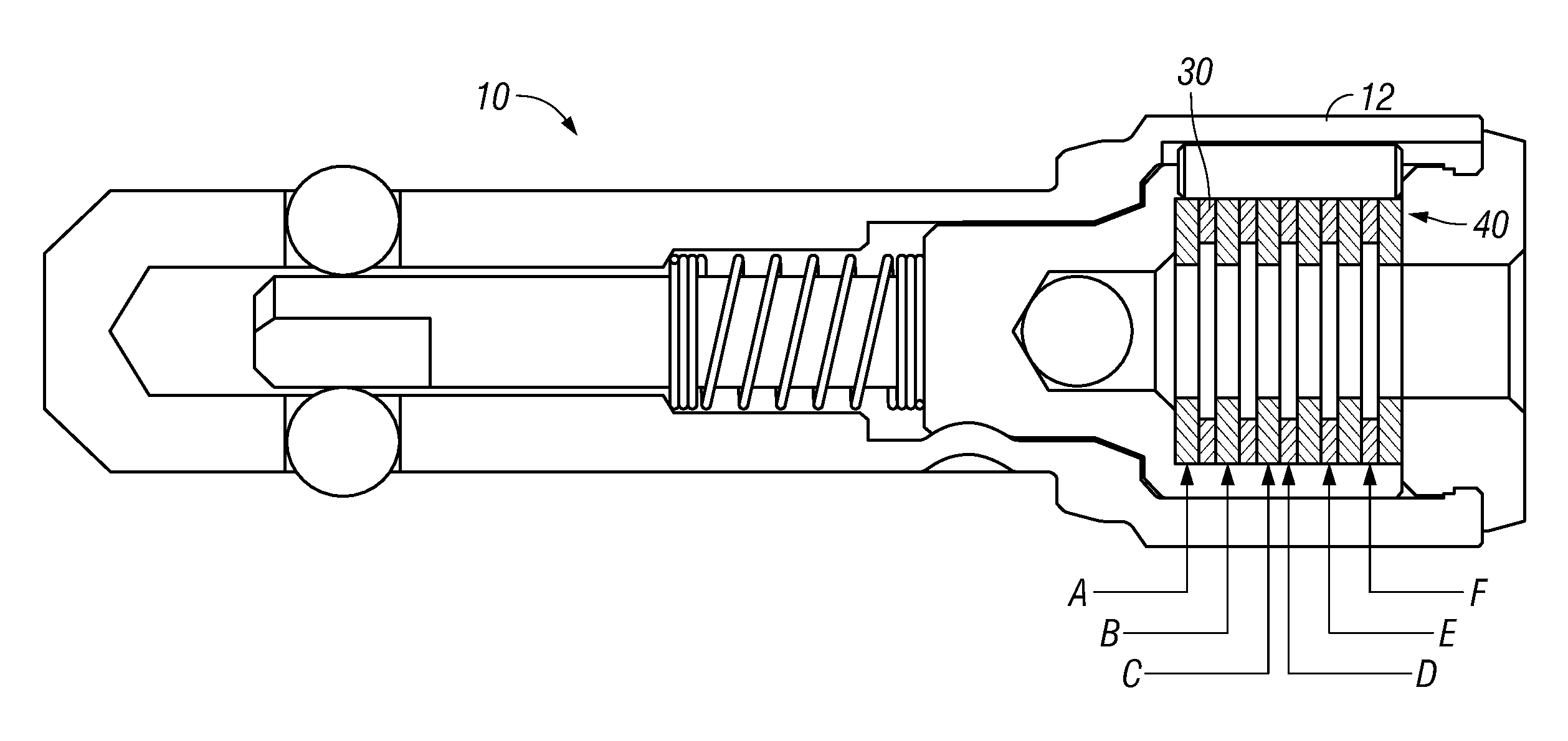
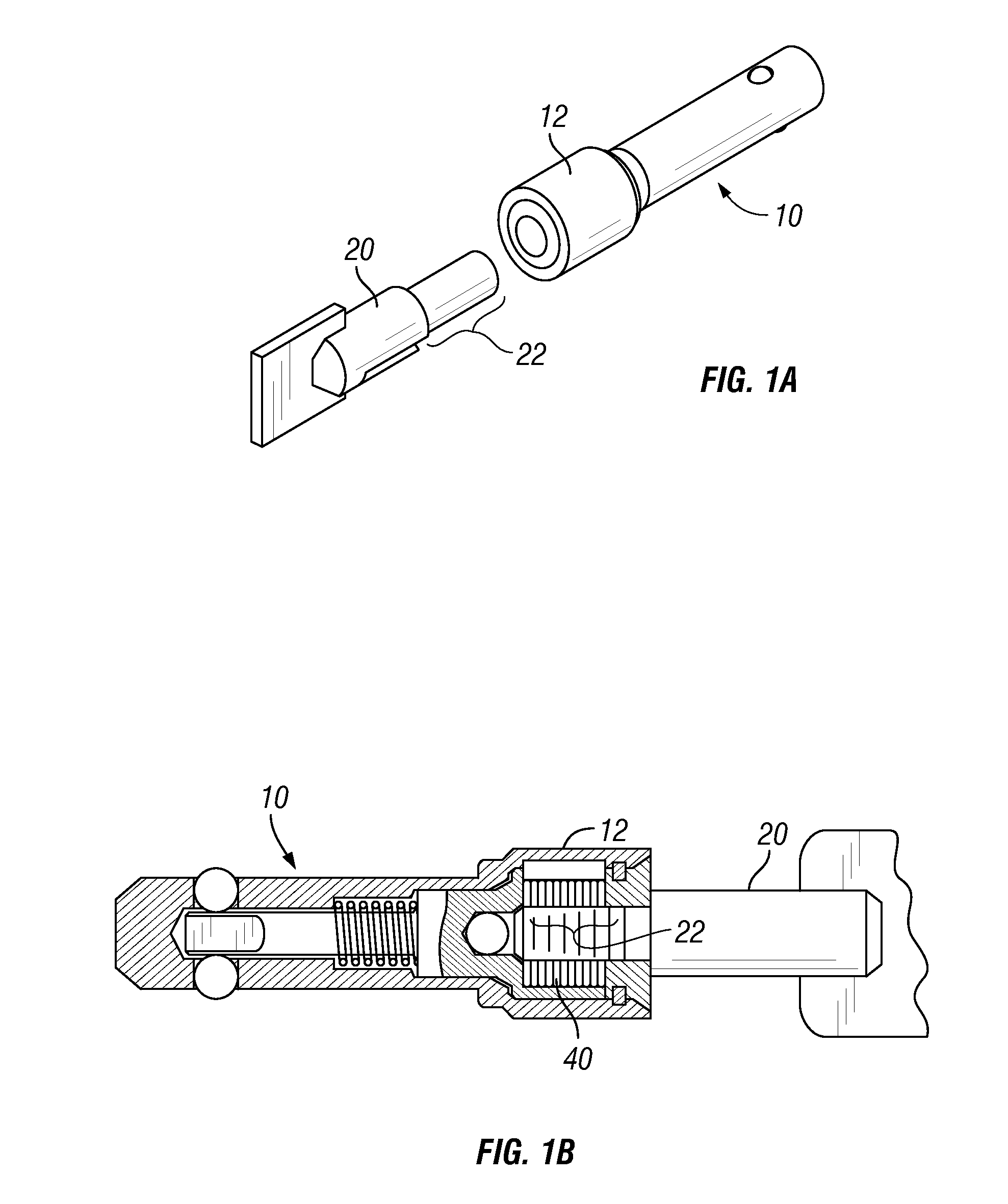
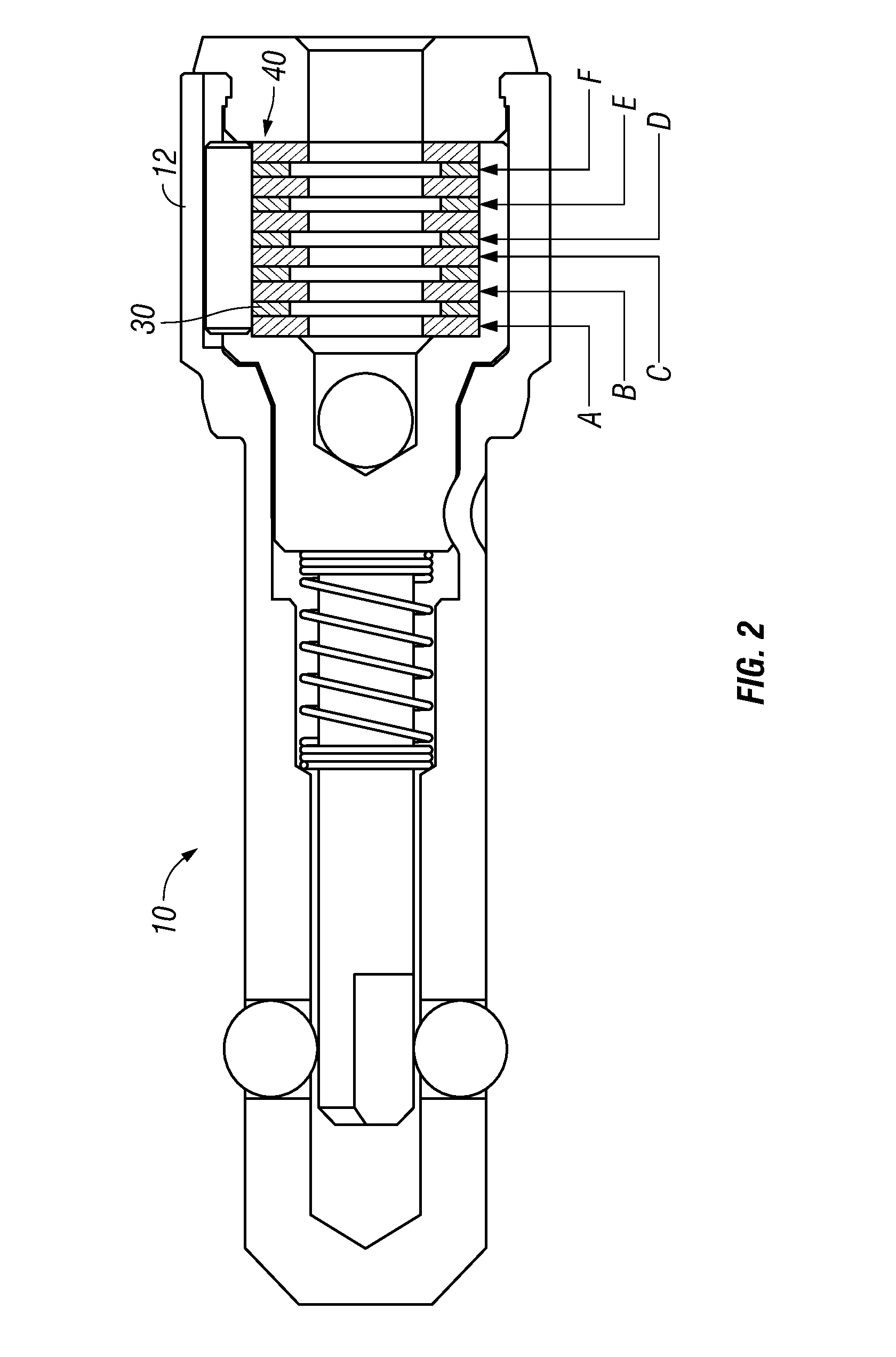
[0033]FIGS. 1A-3C depict a known rotating disk barrel lock 10 and known operating key 20. The barrel lock 10 includes a head portion 12 which contains a series of rotatable disks 40 that are arranged in a stacked relationship. Each rotatable disk 40 is spaced apart from adjacent disks by a spacer 30.

[0034]The key 20 include a series of longitudinally spaced “key cuts” referred to herein as cam surface sections 22. The number of cam surface sections 22 corresponds to the number of disks 40 in the lock and each cam surface section engages a separate disk. In particular, each cam surface section 22 engages spiral disk cam surfaces 24 located in a central aperture 60 of each disk thereby rotating the disks to lock or unlock the lock 10 (FIGS. 3A-3C).

[0035]The operation of the lock mechanism is described more fully in U.S. Pat. No. 5,086,631 and U.S. Patent Application Publication No. 2008 / 0105013, which are both incorporated by reference herein.

[0036]Referring now to FIG. 2, the disks 4...


PUM


Abstract

A rotating disk lock mechanism that includes a lock housing containing a plurality of rotatable disks. Each disk having a central aperture and being positioned in a stack such that the central apertures form a keyway. At least one of the disks includes a reduced central aperture with a diameter that is substantially less than a diameter of at least another one of the central apertures. The combination of the lock mechanism is determined in part by the number of disks with reduced central apertures and their placement in the stack.

Description

FIELD OF THE INVENTION[0001]The present invention relates generally to a rotating disk lock mechanism and more particularly to a rotating disk lock mechanism that provides an enhanced number of potential combinations through the use of rotating disks and keys that include mating surfaces having a reduced size.BACKGROUND OF THE INVENTION[0002]Utility boxes, such as electric meter boxes, are typically secured to prevent unauthorized access to the meter. Many of such boxes are secured through the use of split ring that is placed directly around the meter and locked through the use of a barrel lock.[0003]A preferred type of barrel lock for use with the above-described utility boxes is known as a rotating disk barrel lock. These locks include multiple rotating disks that, when rotated into the proper position via a key, will open the lock. An example of such a rotating disk barrel lock is described in U.S. Pat. No. 5,086,631, which is hereby incorporated by reference in its entirety.[000...

Claims


Application Information

Patent Timeline
Patent Type & Authority Applications(United States)
IPC IPC(8): E05B9/04E05B19/02E05B37/02
CPCE05B21/066E05B67/365E05B35/10Y10T70/443Y10T70/70Y10T70/7141Y10T70/7446Y10T70/7452Y10T70/7463Y10T70/7627Y10T70/7633Y10T70/7689Y10T70/8324
Inventor AGBAY, ANTHONY JOHN
Owner INNER TITE A DIV OF YARA ENG
Why Eureka
Try Eureka