Methods and Systems for Interbody Implant and Bone Graft Delivery

Inactive Publication Date: 2012-03-15
THOMPSON MIS
View PDF0 Cites 76 Cited by
  • Summary
  • Abstract
  • Description
  • Claims
  • Application Information

AI Technical Summary

Benefits of technology

[0009]These and other objects of the invention are achieved in a spinal implant system for positioning and fixing an implant between adjacent vertebrae that includes a spacer, a feed reservoir, and a plunger. The spacer includes a distal end and a proximal end. The spacer also includes top and bottom surfaces spaced by sides. The top and bottom surfaces define a height, and the sides define a width. The height is greater than the width, wherein the spacer may be inserted with its sides oriented toward surfaces of adjacent vertebrae and then rotated into place with the top and bottom surface oriented toward the surfaces of the adjacent vertebrae to maintain a desired space between the adjacent vertebrae. In such an application of the device, nerve root retraction can be reduced and improved disc height restoration achieved. The spacer also includes cutouts into each of the sides forming a web separating top and bottom caps at least at the proximal end of the spacer. The thickness of the web decreases proximally to form a wedge having a leading edge proximate to the proximal end of the spacer. The wedge is sized and configured to aid distribution of bone graft material to either side of the wedge, wherein bone graft material is supplied to a site of interest is distributed to at least one side of the wedge. Thus, the interbody device is placed, rotated to restore disc height, and bone then passed on either side of the implant allowing for better and more bone graft delivery into the disc interspace. The feed reservoir defines a passageway through which bone graft material may be delivered to the spacer when the spacer is positioned as desired between adjacent vertebrae. The feed reservoir includes an alignment feature configured to align the feed reservoir with the spacer so that bone graft material delivered to the spacer through the feed reservoir is distributed to at least one side of the wedge of the spacer. The plunger is configured to be accepted by the passageway of the feed reservoir, and is configured to help advance bone graft material along a length of the feed reservoir.

Problems solved by technology

Most of these cages are limited to only a few cubic centimeters of bone graft material thus limiting the fusion area achieved.
Many known procedures for spinal fusion, however, still are more invasive than desired.
Additionally, many known procedures do not provide the level of control over the delivery and placement of the bone graft material as could be desired.
Additionally, current interbody devices only allow for a limited application of bone material (i.e., cages), and because of their relative size place the neural elements at risk during placement, often resulting in undersized implants being placed.

Method used


Image

  • Methods and Systems for Interbody Implant and Bone Graft Delivery
  • Methods and Systems for Interbody Implant and Bone Graft Delivery
  • Methods and Systems for Interbody Implant and Bone Graft Delivery

Examples


Embodiment Construction

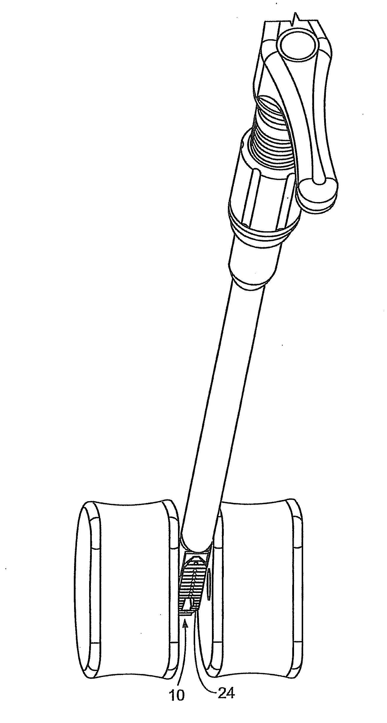
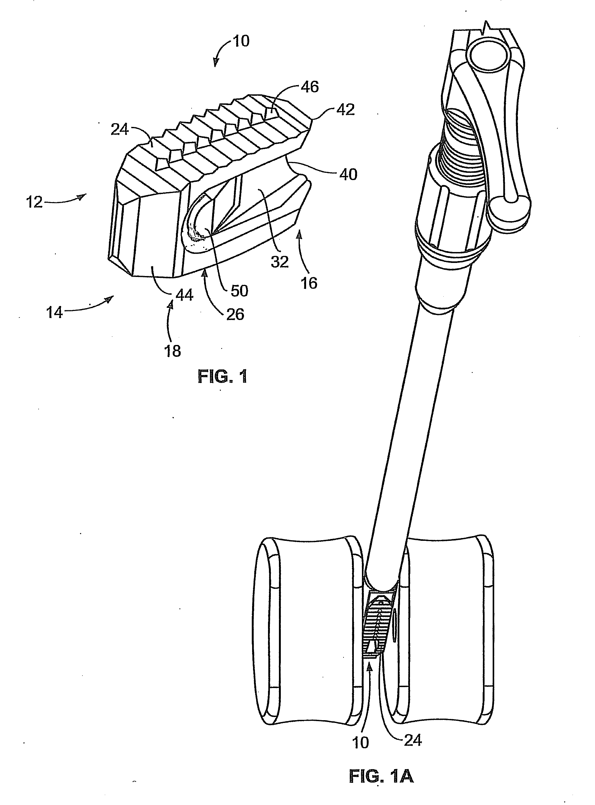
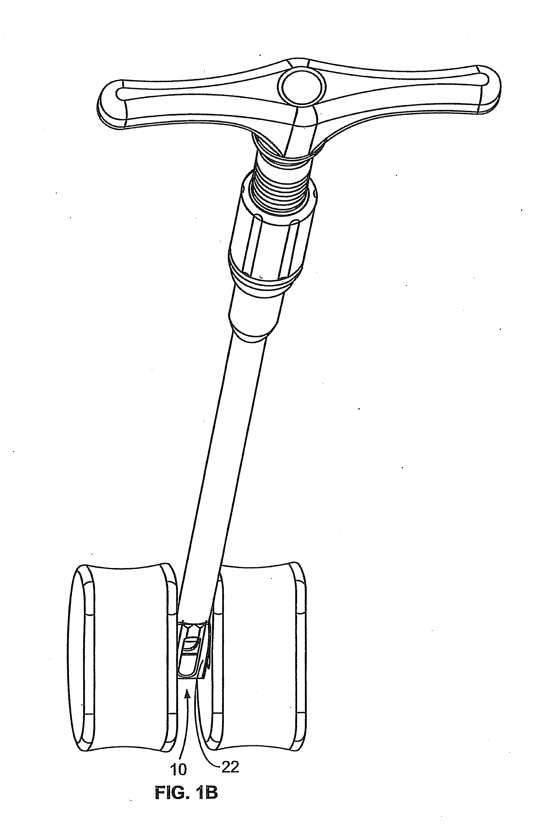
[0044]FIG. 1 illustrates a perspective view of a spinal implant, or spacer, 10; FIG. 2 illustrates a side view of the spacer 10; FIG. 3 illustrates a top view of the spacer 10; and FIG. 4 provides an end view (looking from the proximal end) of the spacer 10. The spacer 10 is sized and adapted to maintain a desired spatial relationship between adjacent vertebrae. Different sizes of spacers are used to accommodate different procedures and / or sizes of patient anatomy. The spacer 10 may, for, example, be made of PEEK (polyether ether ketone), titanium, carbon fiber, bone allograft, or a plurality of materials. The spacer 10 includes a top side 12 and a bottom side 14. (The spacer 10 illustrated in FIGS. 1-4 is symmetric, so “top” and “bottom” sides may be interchangeable). Alternatively, the spacer can be of greater height distally to allow for lordotic disc height restoration. The spacer 10 also includes a proximal end 16 and a distal end 18. The proximal end 16 is the end of the space...


PUM


Abstract

A bone graft system for providing bone graft material to a site of interest includes a multiple unit bone graft material loading device and a conduit. The multiple unit bone graft material loading device is configured to accept a plurality of pre-formed bone graft material units and includes a plurality chambers configured to accept a pre-formed bone graft unit. The conduit includes a first opening and second opening. The first opening is operably connected with the multiple unit bone graft material loading device to accept bone graft material from the multiple unit bone graft material loading device. The second opening is configured to deliver bone graft material to a site of interest.

Description

CROSS-REFERENCE TO RELATED APPLICATION[0001]This application claims priority to “Methods and Systems for Interbody Implant and Bone Graft Delivery,” U.S. Patent Application No. 61 / 377,691, Attorney Docket No. 23079US01, filed Aug. 27, 2010, the entire content of which is hereby incorporated by reference.STATEMENT REGARDING FEDERALLY SPONSORED RESEARCH OR DEVELOPMENT[0002]None.BACKGROUND OF THE INVENTION[0003]The present invention relates to systems and methods for providing spinal implants, for example, to be used in connection with spinal fusion.[0004]Spinal fusion is a surgical procedure that fuses two or more vertebrae together using bone graft materials supplemented with devices. Spinal fusion may be performed for the treatment of chronic neck and / or back pain, trauma, and neoplasms. Spinal fusion can be used to stabilize and eliminate motion of vertebrae segments that may be unstable, or move in an abnormal way, that can lead to discomfort and pain. Spinal fusion may be perform...

Claims


Application Information

Patent Timeline
IPC IPC(8): A61B17/56A61M5/00
CPCA61F2/4465A61F2310/00359A61F2/4611A61F2/4644A61F2002/3008A61F2002/30266A61F2002/30281A61F2002/305A61F2002/30828A61F2002/3083A61F2002/30843A61F2002/30892A61F2002/4627A61F2002/4628A61F2310/00017A61F2310/00023A61F2310/00161A61F2/447A61B17/8833
Inventor PEPPER, JOHN R.FARLEY, DANIEL K.MARTIN, CHRISTOPHER T.ZALUCHA, STEPHANIEPEREZ-CRUET, MIGUELANGELO J.
Owner THOMPSON MIS
Why Eureka
Try Eureka