Proper frequency planning in a synthetic instrument RF system

a synthetic instrument and frequency planning technology, applied in the field of synthetic instrument clocks, can solve the problems of difficult to meet the goal, high frequency gain was either not available or very expensive, etc., and achieve the effect of improving the noise floor and dynamic range of the synthetic instrument system, improving the noise floor, and improving the noise floor

Active Publication Date: 2012-03-15
BAE SYST INFORMATION & ELECTRONICS SYST INTERGRATION INC
View PDF0 Cites 0 Cited by
  • Summary
  • Abstract
  • Description
  • Claims
  • Application Information

AI Technical Summary

Benefits of technology

[0008]The preferred embodiment of the invention includes a method of generating an analog-to-digital converter (ADC) sampling clock for an SI system. The preferred embodiment improves the clocking of the ADC in a synthetic instrument to improve the noise floor and dynamic range of a synthetic instrument system. The method begins by amplifying an input clock to produce an amplified clock. This amplified clock is then filtered to produce a filtered clock. Preferably, the amplified clock is filtered with a narrow bandpass filter that can be a second order filter. The ADC of the synthetic instrument is clocked with the filtered clock to sample the input data at a sampling frequency. The input data is carried by an intermediate frequency (IF) signal and can have an input frequency that corresponds to a second or higher Nyquist zone so that the input frequency is above the sampling frequency of the ADC. The method switches the filtered clock off a clock path of the ADC when the ADC is not in use. When there is input data for the ADC to filter, the method switches the filter clock onto the path of the ADC so that the ADC can sample the input data. This switching can improve the noise floor of more than 15 dB over a significant bandwidth.

Problems solved by technology

High frequency gain was either not available or was very expensive.
This goal is difficult to meet when using an IF and frequency plan with an IF designed to pass narrow bandwidth signals.

Method used


Image

  • Proper frequency planning in a synthetic instrument RF system
  • Proper frequency planning in a synthetic instrument RF system
  • Proper frequency planning in a synthetic instrument RF system

Examples


first embodiment

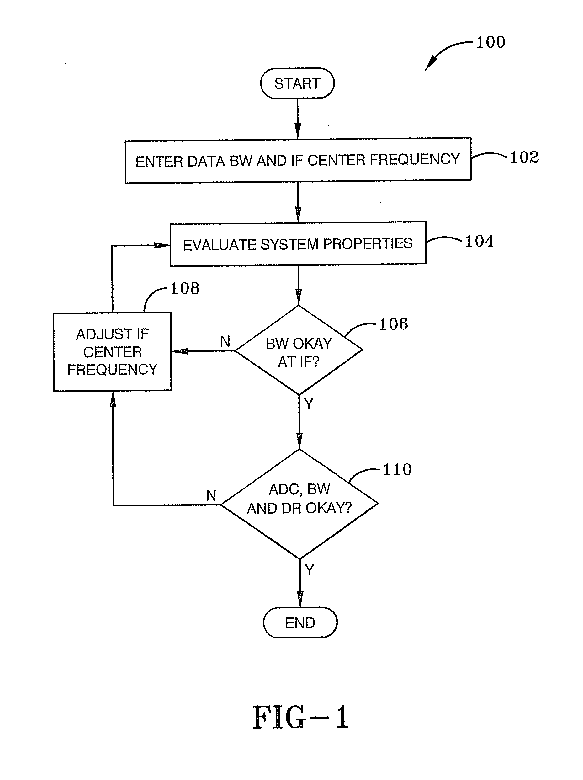
[0030]FIG. 1 illustrates a method 100 used to plan the intermediate frequency (RF) and the bandwidth of and analog-to-digital converter (ADC). For purposes of simplicity of explanation, FIG. 1 and the other illustrated methodologies of other figures are shown and described as a series of blocks. It is to be appreciated that the methodologies are not limited by the order of the blocks, as some blocks can occur in different orders and / or concurrently with other blocks from that shown and described. Moreover, less than all the illustrated blocks may be required to implement an example methodology. Blocks may be combined or separated into multiple components. Furthermore, additional and / or alternative methodologies can employ additional, not illustrated blocks.

[0031]FIG. 1 illustrates the interaction between the IF bandwidth, IF center frequency, and the interaction of the ADC sampling clock selection. The process converges once the input signal bandwidth properties are well defined. A ...

second embodiment

[0052]FIG. 9 illustrates a second embodiment method 900 for frequency planning a synthetic instrument unit. The method 900 begins by selecting an intermediate frequency (IF) that is carrying input data, at 902. The frequency is selected based on the architecture of synthetic instrumentation units such as receivers, filters, antennas, mixers and other components as understood by those of ordinary skill in the art. Selecting the IF can be an iterative process that is successful when the system bandwidth, the dynamic range (DR), sampling clock of an ADC and other features of the SI are radically synchronized.

[0053]A system bandwidth (BW) of the synthetic instrument unit is determined at 904. Next, a determination is made to determine if the system bandwidth (BW) is above a first tolerance, at 906. The IF is adjusted, at 908, when the system BW is not above the first tolerance to produce an updated IF. When the system BW is above the first tolerance, the method 900 selects an analog-to-...

third embodiment

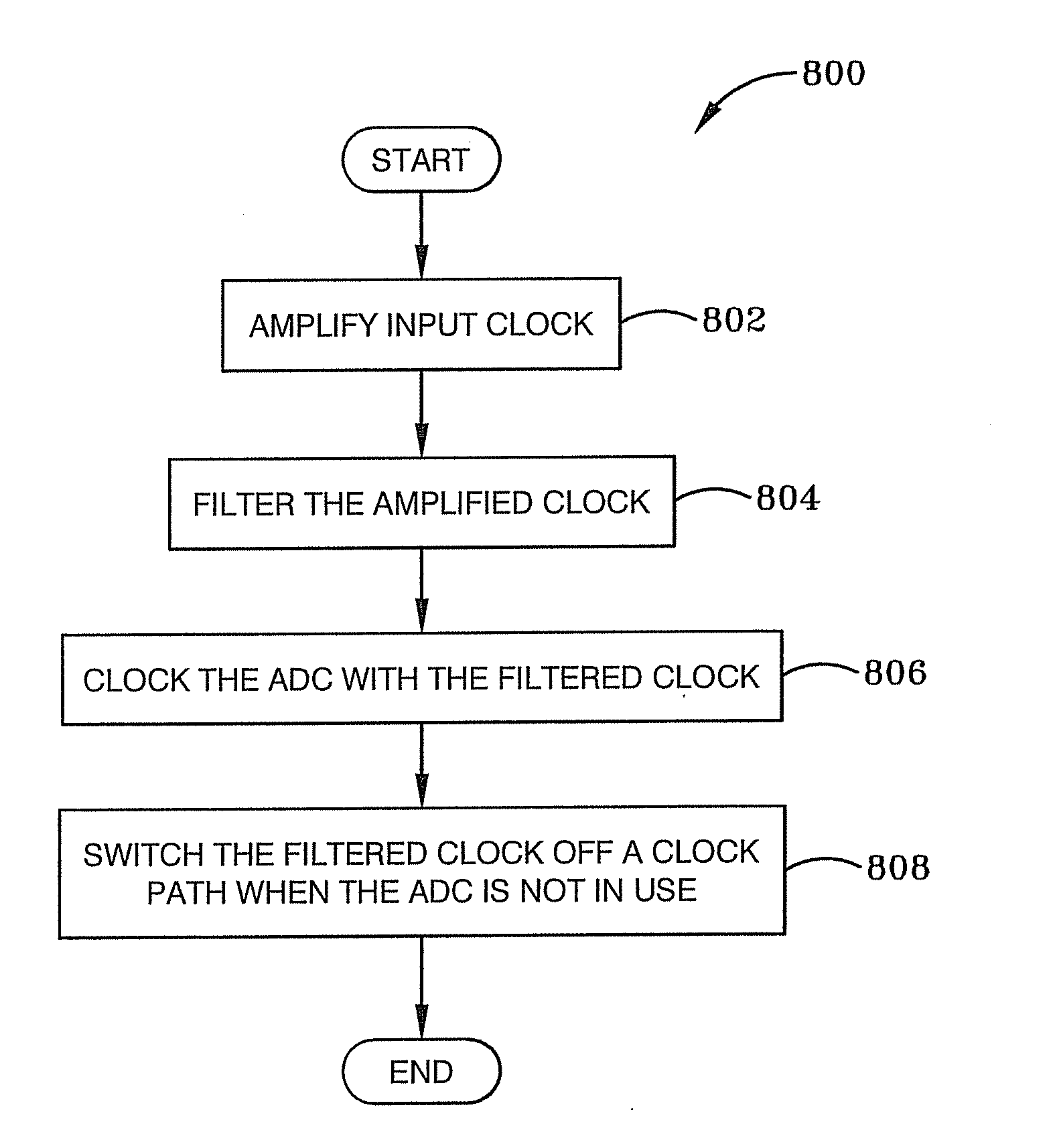
[0054]In other configurations of the third embodiment, an amplifier is selected that is capable of amplifying the ADC sampling clock prior to filtering the ADC sampling clock. An ADC can also be selected based on the IF where the ADC can be used to filter the input data based on the ADC sampling clock frequency. The IF and the ADC sampling clock can be selected so that the IF has a frequency that is about four times greater than the ADC sampling clock frequency.

[0055]In addition to determining if the BW is satisfactory, at 906, the method 900 can also determine if a BW of the ADC is satisfactory. If the system BW is not satisfactory, then the IF is adjusted to produce an updated IF. The determining if the BW of the ADC is within a BW window is performed after selecting an intermediate IF. The method 900 can also determine if the dynamic range (DR) of the input data is satisfactory. The IF is adjusted when the DR is not within the DR window to produce an updated IF.

[0056]In summary, ...


PUM


Abstract

A system and method for clocking in analog-to-digital (ADC) converter in a synthetic instrument unit is presented. A method begins by applying an input clock to an amplifier to produce an amplified clock. The amplified clock is filtered to produce a filtered clock. The ADC of this synthetic instrument unit is clocked with the filtered clock. The input frequency of the ADC corresponds to a second or higher order Nyquist zone that is above the sampling frequency of the ADC. The input data is carried by an intermediate frequency (IF) signal. The filtered clock of ADC is switched off a clock path of the ADC when the ADC is not in use.

Description

BACKGROUND OF THE INVENTION[0001]1. Field of Invention[0002]The current invention relates generally to apparatus, systems and methods for synthetic instruments. More particularly, the apparatus systems and methods relate to clocks for synthetic instruments. Specifically, the apparatus, systems and methods relate to amplifying and filtering clocks for use in synthetic instruments.[0003]2. Description of Related Art[0004]Synthetic Instrument (SI) units are modern measurement and stimulus systems. Unlike traditional instrumentation systems, the SI user may not be constrained by legacy frequency plans. Traditional downconverter frequency plans were born from technology available in the 1960s and 1970s. High frequency gain was either not available or was very expensive. Therefore, the bulk of the system's gain was obtained at a relatively low Intermediate Frequency (IF) and was usually passed along to the Analog-to-Digital Converter (ADC). Typical IF choices were 455 KHz, 10.7 MHz or 21....

Claims


Application Information

Patent Timeline
Patent Type & Authority Applications(United States)
IPC IPC(8): G06F1/04
CPCG06F1/04H03M1/1255H03M1/0626H03M1/002
Inventor ESTRADA, ANTHONY
Owner BAE SYST INFORMATION & ELECTRONICS SYST INTERGRATION INC
Why Eureka
Try Eureka