Anti-spin system for the head of a cone crusher

a construction system and cone crusher technology, applied in the direction of solid separation, agriculture, chemistry apparatus and processes, etc., can solve the problems of high inconvenient condition, no material in the crushing cavity to exert frictional braking force between the cone head, and abrupt braking of the latter against the great inertia force of the rotating mass, etc., to reduce the frictional contact area, reduce the radial bearing capacity of the cone head, and reduce the frictional dragging force of the con

Active Publication Date: 2012-03-15
METSO BRASIL IND E COMML LTDA
View PDF0 Cites 0 Cited by
  • Summary
  • Abstract
  • Description
  • Claims
  • Application Information

AI Technical Summary

Benefits of technology

[0010]In view of the problems mentioned above, it is one of the objects of the present invention to provide an anti-spin system for the head of a cone crusher of the type considered herein, presenting a simple construction of a relatively low cost and which can be easily installed and maintained, preventing the cone head from rotating with the eccentric element, when the crusher is in the “no-load” operation.
[0012]According to a first aspect of the invention, the anti-spin system comprises a braking bush, carried by one of the parts defined by the cone head and by the structure, and an annular shoe carried by the other of said parts, the braking bush and the annular shoe being pressed against each other, by action of the inertial centrifugal force acting on the cone head upon “no-load” operation of the crusher, so as to generate a friction force opposite and superior to the friction force generated between the cone head and the eccentric element and to prevent the cone head from being rotationally dragged by the eccentric element.
[0015]The constructive system defined above provides a simple and strong frictional braking means, capable of preventing the rotation of the cone head with the eccentric element, whenever no material is being crushed in the crushing cavity.
[0016]Apart from providing a braking force in a direction opposite to that of the frictional dragging force between the cone head and the eccentric element, the system of the present invention can also lead to a reduction of said frictional dragging force, by reducing the axial extension of the radial bearing of the cone head around the eccentric element, in the minimum eccentricity region of the latter.
[0017]The constructive characteristic cited above allows to substantially reduce the frictional contact area, that is, the radial bearing area between the cone head and the eccentric element, in a region of said bearing which is opposite to that supporting the radial crushing loads in the “on-load” operation of the crusher, but which defines the region onto which the cone head exerts a greater pressure against the eccentric element, as a function of the inertial centrifugal force generated on the cone head, upon “no-load” operation of the crusher. Thus, the present constructive system also allows reducing the frictional dragging force of the cone head by the eccentric element, without reducing the radial bearing capacity of the cone head around the eccentric element, in the region of the latter which is subject to the radial crushing loads in the “on-load” operation.

Problems solved by technology

However, during the “no-load” operation of the crusher, that is, when no material is being crushed in the crushing cavity, and the eccentric element continues to rotate around the vertical axle, there is no material in the crushing cavity to exert a frictional braking force between the cone head and the upper housing mounted to the structure of the crusher.
Nevertheless, in said “no-load” operating condition, when the material to be crushed is fed into the crushing cavity, it makes frictional contact simultaneously with the stationary crushing surface of the upper housing and with the rotating crushing surface of the cone head, provoking an abrupt braking of the latter against the great inertia force of its rotating mass.
This operational condition is highly inconvenient, since it causes an intense wear of the crushing surfaces, usually defined by hard-material coatings applied to the cone head and to the upper housing.
Another negative aspect of the cone head rotating jointly with the eccentric element is the tendency of the crusher to violently throw, outwardly from the crushing cavity, the first particles of stone, ore, coal and others introduced into the crusher operating in the “no-load” mode, under the risk of causing injury to the operators and damages to the machine.
However, this solution presents, as drawbacks, the high cost of the clutch and of its assembly, as well as maintenance difficulties.
Furthermore, in the “on-load” operational condition, the cone head is frequently forced to rotate in the locking direction of the clutch, damaging the latter.

Method used


Image

  • Anti-spin system for the head of a cone crusher
  • Anti-spin system for the head of a cone crusher
  • Anti-spin system for the head of a cone crusher

Examples


Embodiment Construction

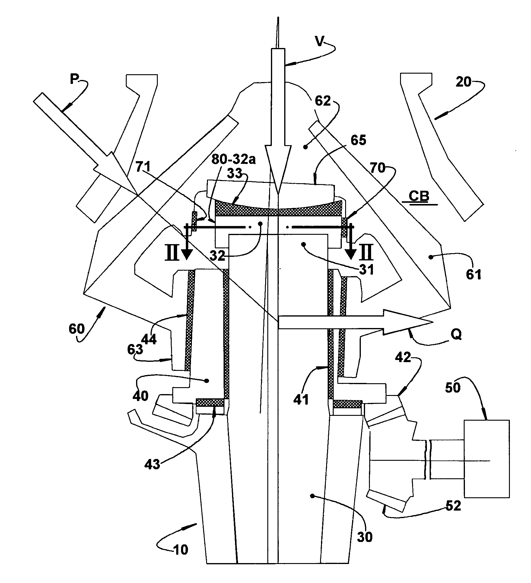
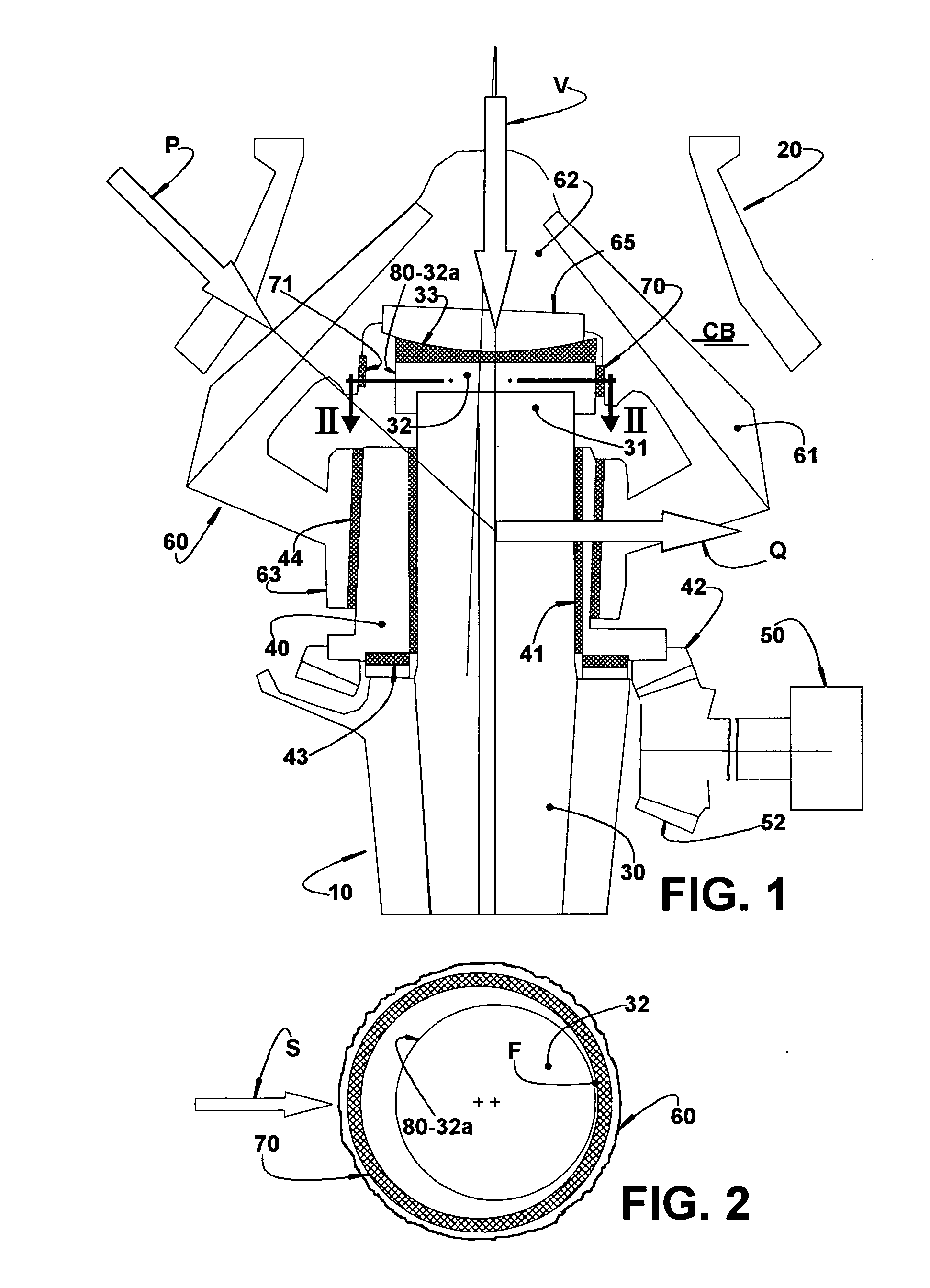
[0026]As previously mentioned, the invention is applied to a cone crusher of the type illustrated in FIG. 1 and which comprises a structure 10, on which is mounted a conical upper housing 20 constructed by any of the well known prior art manners and which is internally provided with a lining (not illustrated), in a material adequate to withstand the crushing forces. It should be understood that the particular constructive characteristics of the structure 10 are not described herein, since they have no effect on the construction or function of the anti-spin system object of the present invention.

[0027]The crusher further comprises a vertical axle 30, inferiorly fixed to the structure 10 and presenting a free upper end 31 which is generally positioned in the interior of the upper housing 20.

[0028]Around the vertical axle 30 is rotatively mounted, with the interposition of an inner tubular bushing 41, a tubular eccentric element 40 provided with a ring gear 42 which is engaged to a pin...


PUM


Abstract

The anti-spin system is applied to a cone crusher having a structure (10) carrying an upper housing (20) and a vertical axle (30); an eccentric element (40) to be rotated around the vertical axle (30); and a cone head (60) disposed inside the upper housing (20) and being axially and rotatively supported on the structure (10) and radially supported around the eccentric element (40). The anti-spin system comprises a braking bush (70) carried by the cone head (60) or by the structure (10), and an annular shoe (80) carried by the other of said parts, which are pressed against each other, by action of the inertial centrifugal force acting on the cone head (60), upon “no-load” operation of the crusher, to generate a friction force opposite and superior to that generated between the cone head (60) and the eccentric element (40) and to prevent the latter from rotatively dragging the cone head (60).

Description

FIELD OF THE INVENTION[0001]The present invention relates to a constructive system applied to a cone crusher of the type which comprises a structure, an upper housing and a vertical axle mounted in the structure, and a conically shaped head disposed in the interior of the ,upper housing to define a crushing cavity therewith and which is displaced, in an oscillating movement around the vertical axle, by an eccentric element radially supporting the head and which is rotated by an adequate drive mechanism.[0002]More specifically, the present invention refers to a constructive system for preventing the head of said crusher from rotating jointly with the eccentric element when the crusher is in the “no-load” operation, that is, when no material is being crushed in the interior of the crushing cavity.BACKGROUND OF THE INVENTION[0003]In the cone crushers of the type defined above, when the material to be crushed is fed into the crushing cavity, this material is simultaneously frictioned ag...

Claims


Application Information

Patent Timeline
Patent Type & Authority Applications(United States)
IPC IPC(8): B02C2/00
CPCB02C2/04
Inventor NIKLEWSKI, ANDRZEJBARSCEVICIUS, PAULO
Owner METSO BRASIL IND E COMML LTDA
Why Eureka
Try Eureka