Temperable three layer antirefrlective coating, coated article including temperable three layer antirefrlective coating, and/or method of making the same
a three-layer antirefrlective coating and coating technology, applied in coatings, instruments, optics, etc., can solve the problems of creating additional problems, undesirable tempering coat methods, and difficult to so as to reduce the reflection of visible light and achieve optimal refraction index
- Summary
- Abstract
- Description
- Claims
- Application Information
AI Technical Summary
Benefits of technology
Problems solved by technology
Method used
Image
Examples
example 1
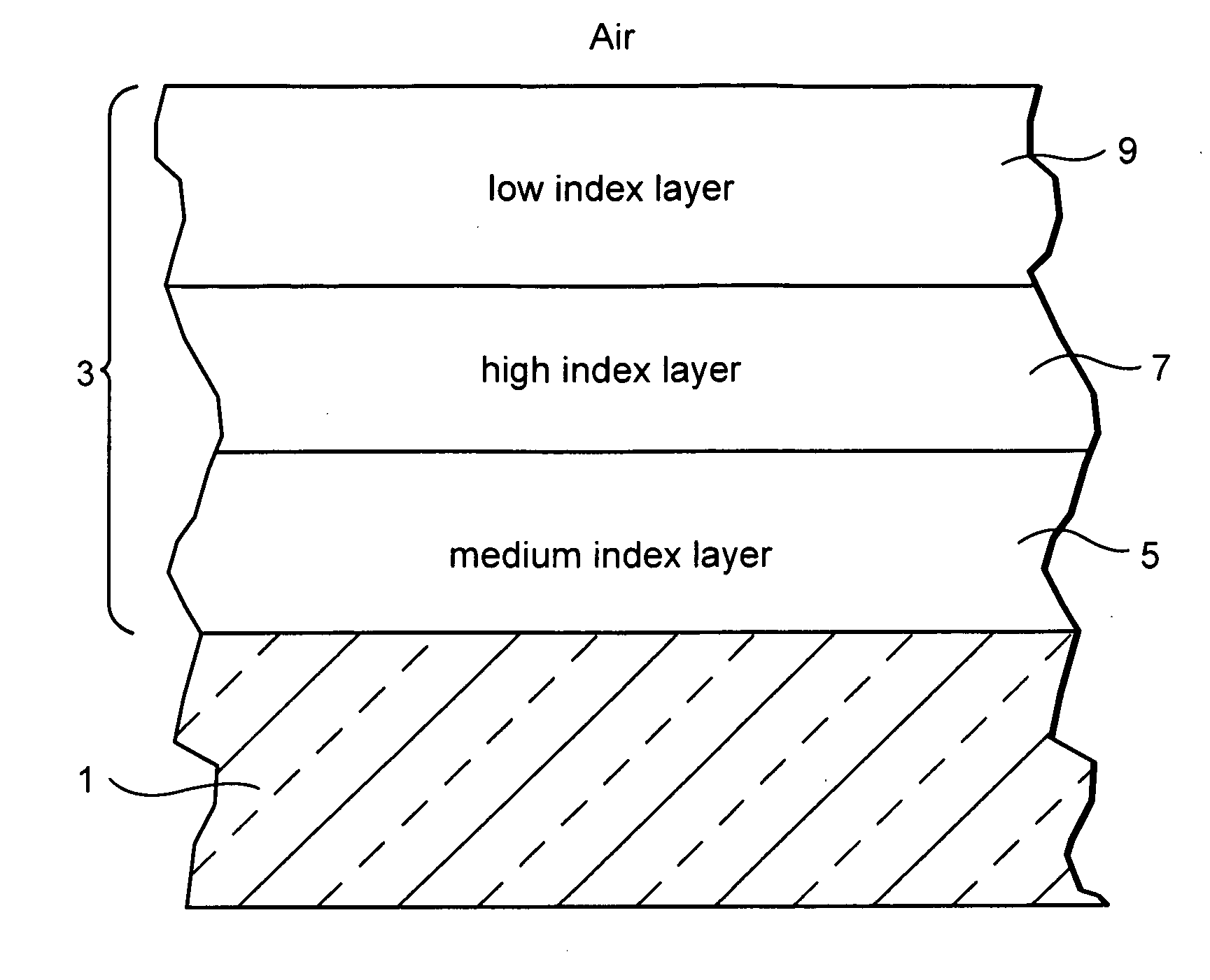
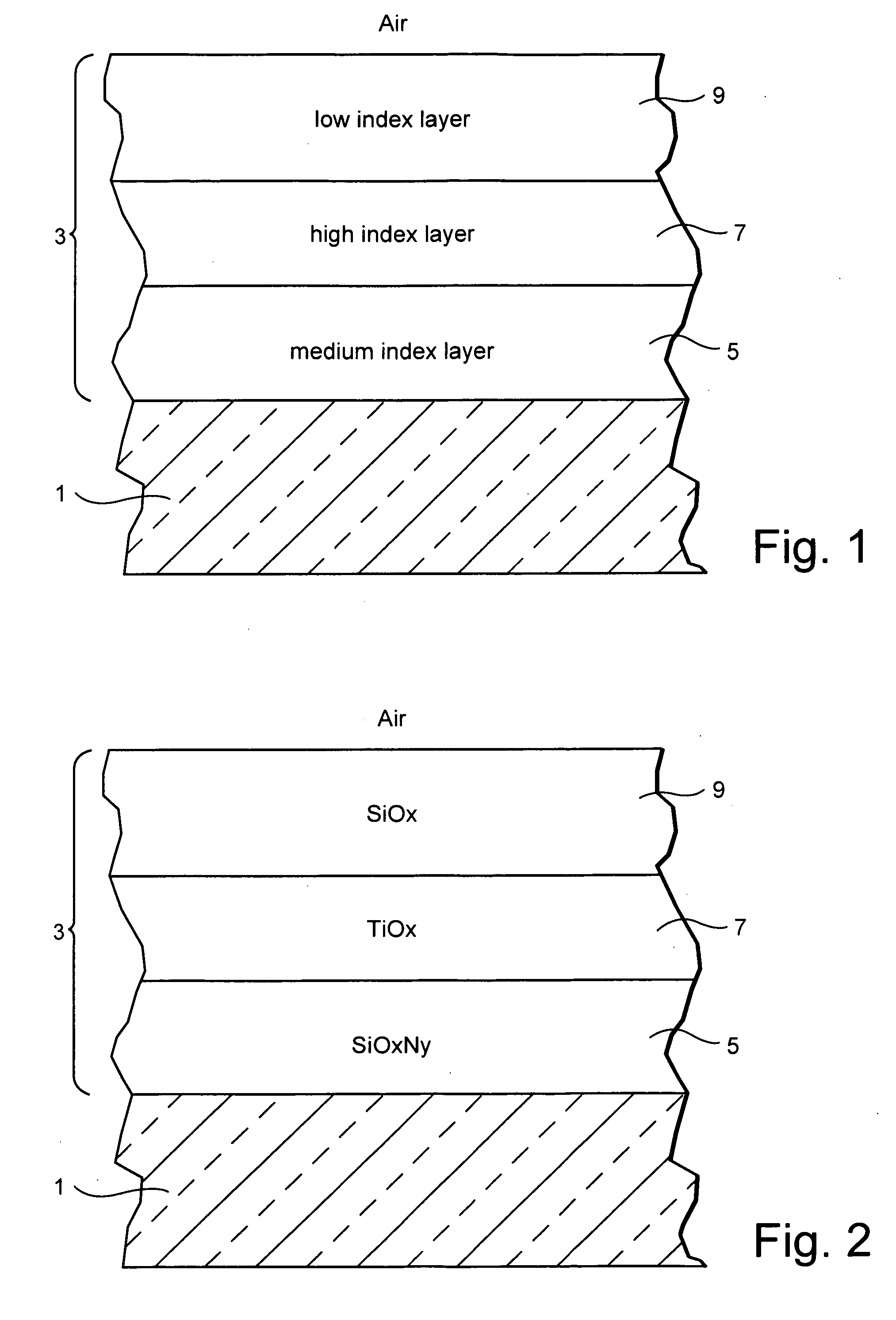
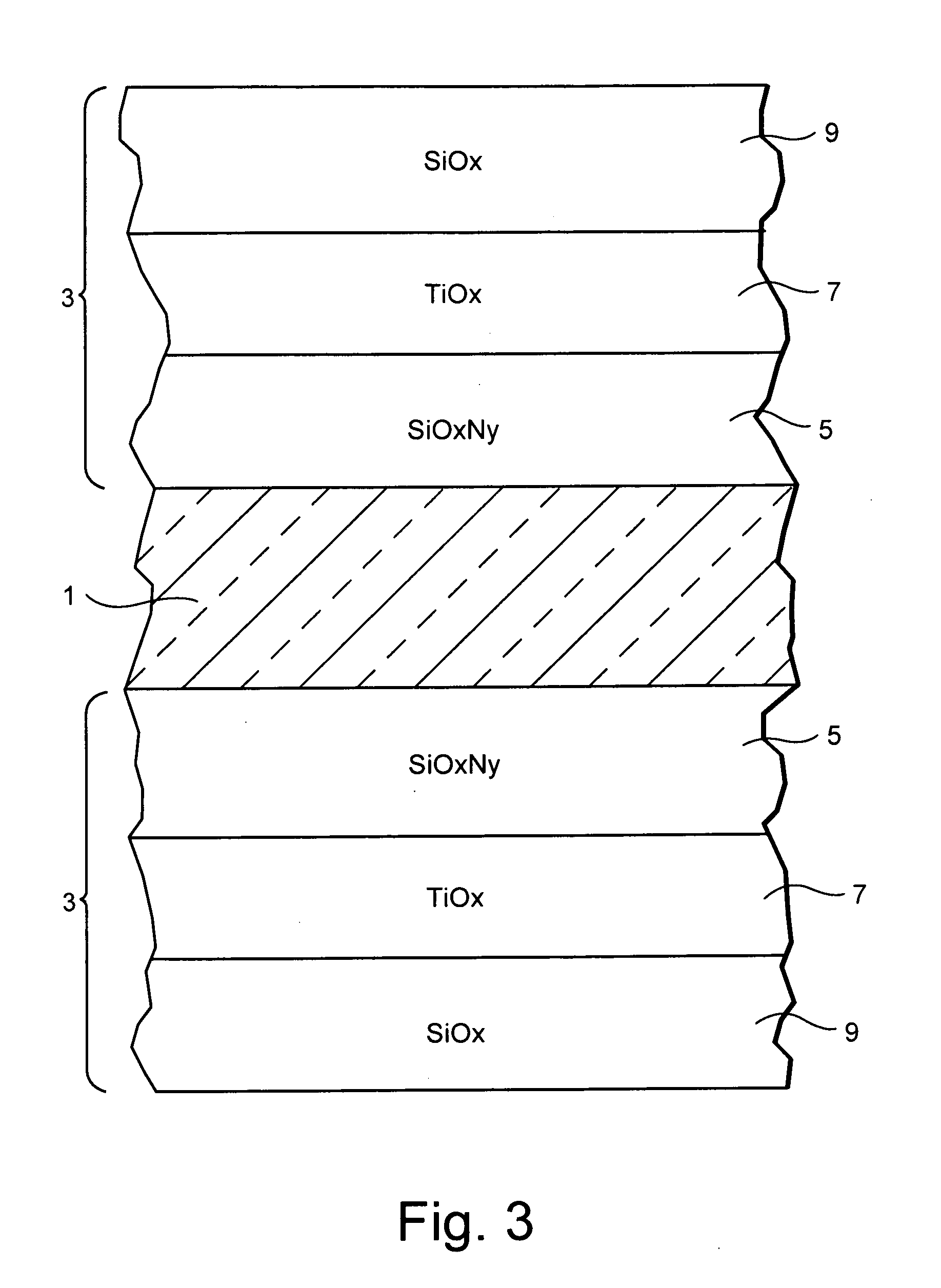
[0060]An Example AR coating 3 was made as follows: SiOxNy layer 5 (medium index layer) about 95 nm thick, TiO2 layer 7 (example high index layer) about 21 nm thick, and SiO2 layer 9 (example low index layer) about 105 nm thick. The clear glass substrate was about 5 mm thick, and was soda lime silica type glass. Each of layers 5, 7, and 9 was deposited on the glass substrate 1 by sputtering a target(s). The coating 3 was provided on only one major surface of the glass substrate in certain instances as shown in FIG. 1, but may be provided on both major surfaces of the glass substrate in other instances as shown in FIG. 3. The coating was tempered at 650 degrees C. for 10 minutes.
[0061]FIG. 4 is a graph showing a comparison of the first surface reflectivity of an as-coated and a tempered / heat-treated three layer visible AR coating at an 8 degree incident angle using White Light. FIG. 4 illustrates the reflection spectra of an example having SiOxNy adjusted to achieve a refractive index...
example 2
[0069]A temperable AR coating was applied to both surfaces of a glass substrate (e.g., a double sided coating was made).
[0070]The double-sided coating (as shown in FIG. 3) also maintains its optical and aesthetic qualities after tempering / heat-treatment processes, when coated on the Sn side of float glass, without the need for any additional surface preparation such as polishing. The coating design described in the preceding paragraphs with respect to Example 1 can be applied to the second surface (or Sn side) of the glass to reduce the overall reflection from both interferences.
[0071]FIG. 10 illustrates the light transmission achieved with the above-described design applied to both surfaces of low iron glass before and after tempering / heat-treating. The photopic light transmission increases after exposure to a tempering environment and exceeds 99% at normal incidence on 3.2 mm low iron glass.
[0072]FIG. 11 illustrates example ranges of physical thicknesses and refractive indices for...
PUM
| Property | Measurement | Unit |
|---|---|---|
| thickness | aaaaa | aaaaa |
| thickness | aaaaa | aaaaa |
| thickness | aaaaa | aaaaa |
Abstract
Description
Claims
Application Information
 - R&D
- Intellectual Property
- Life Sciences
- Materials
- Tech Scout
- Unparalleled Data Quality
- Higher Quality Content
- 60% Fewer Hallucinations
Browse by: Latest US Patents, China's latest patents, Technical Efficacy Thesaurus, Application Domain, Technology Topic, Popular Technical Reports.
© 2025 PatSnap. All rights reserved.Legal|Privacy policy|Modern Slavery Act Transparency Statement|Sitemap|About US| Contact US: help@patsnap.com


