Image display apparatus

Inactive Publication Date: 2012-03-08
PANASONIC CORP
View PDF10 Cites 7 Cited by
  • Summary
  • Abstract
  • Description
  • Claims
  • Application Information

AI Technical Summary

Benefits of technology

[0008]An advantage of the present invention is to provide an image display apparatus in which especially the temperature of the red color laser light source apparatus is not increased by a long period of use, and thereby image quality deterioration is prevented.
[0009]In view of the above circumstances, the present invention provides an image display apparatus which includes the following. Specifically, the image display apparatus includes a case that has an air inlet port and an exhaust port; a cooling air passage that is formed by connecting the air inlet port and the exhaust port; and an optical unit that is provided within the case. The optical unit includes a red color laser light source, a green color laser light source, and a blue color laser light source, and these laser light sources are positioned in the cooling air passage. Further, the image display apparatus has an air blower that cools the laser light sources of the respective colors by introducing air from the air inlet port and exhausting air from the exhaust port; and a lens that is provided on the light-emitting side of the laser light sources. The red color laser light source is positioned closer to an upstream side of the cooling air passage than the green color laser light source and the blue color laser light source.
[0010]Another advantage of the present invention is, in addition to the above-described advantage, to achieve an image display apparatus that can freely change the direction of projecting images. Another advantage is to achieve smooth rotation at the time of changing the projecting direction. For this purpose, a second case having an exhaust port is rotatably provided to a first case having an air inlet port, and a cooling air passage is provided in the first case.
[0011]With this, since the air blower is not included in the second rotatable case, the second case can be made compact and light, which can achieve smooth rotation.
[0012]Another advantage of the present invention is to provide an image display apparatus that can perform efficient heat dissipation by shortening the cooling air passage. For this purpose, a second case having an air inlet port and an exhaust port is rotatably provided to a first case, and a cooling air passage is provided in the second case. With this, since the cooling air passage is formed only in the second case that rotates and has the optical unit, the cooling air passage can be shortened and heat dissipation can be performed efficiently.

Problems solved by technology

In the conventional image display apparatus, however, the quality of projected images deteriorates as the image display apparatus is used for a long period of time.
Basically, temperature increase of the laser light sources will cause decrease of the output.
Consequently, output from the red color laser light source apparatus is easily decreased due to the temperature increase caused by a long period of use of the conventional image display apparatus.
When one of the three color laser light is decreased in this manner, the conventional image display apparatus cannot output high-quality images.

Method used


Image

  • Image display apparatus
  • Image display apparatus
  • Image display apparatus

Examples


embodiment 1

[0028]Hereinafter, embodiment 1 of the present invention will be explained with reference to the drawings.

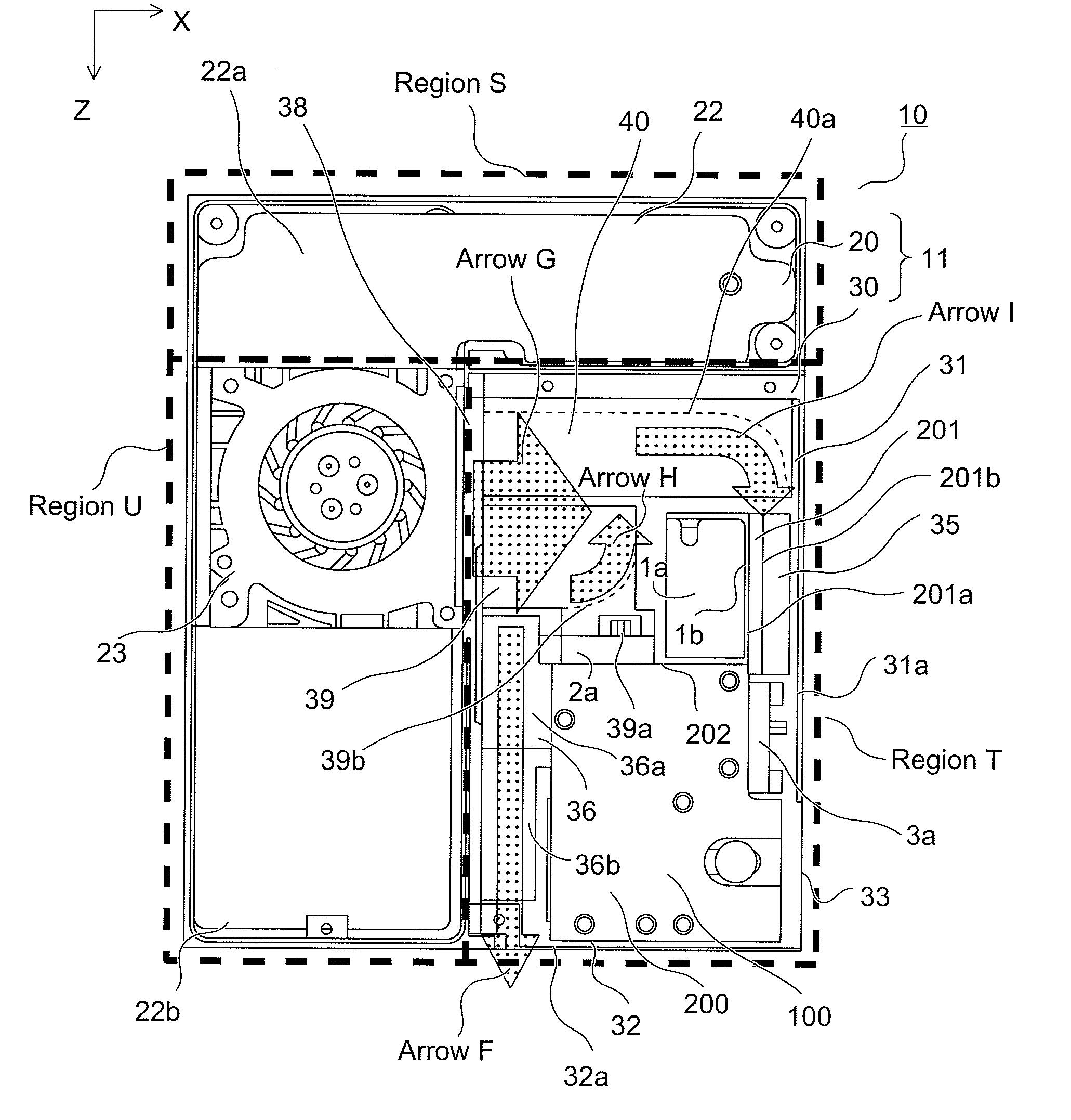
[0029]First, the configuration of the image display apparatus main body will be explained with reference to FIG. 1. FIG. 1 is a schematic perspective view of the image display apparatus main body according to embodiment 1 of the present invention.

[0030]In FIG. 1, the image display apparatus main body 100 uses laser light as a light source and performs magnification and projection on the screen. The image display apparatus main body 100 has three light sources, that is, a green color laser light source apparatus 1, a red color laser light source apparatus 2, and a blue color laser light source apparatus 3. The image display apparatus main body 100 displays an image with the three-color laser light source apparatuses 1-3.

[0031]The green color laser light source apparatus 1 mainly outputs green color laser light by converting non-visible infrared fundamental laser light to a half w...

embodiment 2

[0094]Hereinafter, embodiment 2 of the present invention will be explained with reference to FIG. 8. FIG. 8 illustrates an example of a cooling air passage of the image display apparatus according to embodiment 2 of the present invention. Here, members having similar configuration and feature to embodiment 1 are assigned the same reference numeral, and a detailed explanation is omitted.

[0095]The differences between the present embodiment and embodiment 1 are the position of the cooling fan 23, the position and the configuration of the control base, and the position and the configuration of the fins. These differences will be explained below.

[0096]As shown in FIG. 8, the cooling fan 23 is provided in the opposite direction of arrow X relative to the opening 38, and releases cooling air to the direction of arrow G. The present embodiment is not provided with the guide 24, and the cooling air from the cooling fan 23 directly cools the fin 34. The inlet ports 21a, not shown in the drawi...

embodiment 3

[0104]Hereinafter, embodiment 3 of the present invention will be explained with reference to FIGS. 9-13. The configuration of the image display apparatus according to embodiment 3 is substantially similar to the configuration of embodiment 1 explained in FIG. 1. The difference is that the cooling fan is provided in the tilted portion.

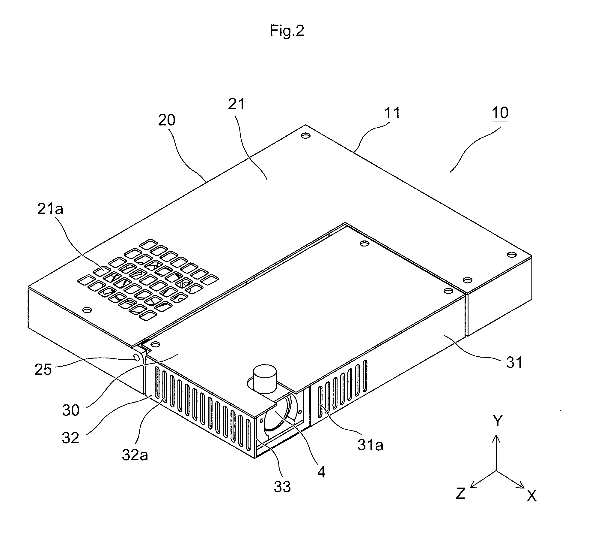
[0105]FIG. 9 is a schematic perspective view of a tilted state of the image display apparatus according to embodiment 3 of the present invention. As shown in FIG. 9, the image display apparatus 10 is configured by the fixed portion 20 and the tilted portion 30. The tilted portion 30 is rotatable relative to the fixed portion 20 around a hinge portion (rotation axis) 25. In sum, the tilted portion 30 is rotatable around an axis perpendicular to a direction of projecting images by the image display apparatus main body 100 and a direction A of taking-in cooling air (see FIG. 10) by the cooling fan 23 (see FIG. 10), thereby allowing the projection angle of ...


PUM


Abstract

The present invention provides an image display apparatus that includes a case having an air inlet port and an exhaust port; a cooling air passage that is formed by connecting the air inlet port and the exhaust port; and an optical unit that is provided within the case. The optical unit includes a red color laser light source, a green color laser light source, and a blue color laser light source, and these laser light sources are positioned in the cooling air passage. Further, the image display apparatus has an air blower that cools the laser light sources of the respective colors by introducing air from the air inlet port and exhausting air from the exhaust port; and a lens that is provided on the light-emitting side of the laser light sources. The red color laser light source is positioned closer to an upstream side of the cooling air passage than the green color laser light source and the blue color laser light source. With this, the temperature of the red color laser light source apparatus is not increased by a long period of use, and thereby image quality deterioration is prevented.

Description

CROSS-REFERENCE TO RELATED APPLICATIONS[0001]The present application claims priority under 35 U.S.C. §119 of Japanese Application Nos. 2010-196383, filed on Sep. 2, 2010, and 2010-223747, filed on Oct. 1, 2010, the disclosures of which are expressly incorporated by reference herein in their entireties.BACKGROUND OF THE INVENTION[0002]1. Field of the Invention[0003]The present invention relates to an image display apparatus in which a laser light source apparatus using a semiconductor laser is incorporated.[0004]2. Description of Related Art[0005]In recent years, laser light has drawn attention as a light source of an image display apparatus which can perform large-screen display, and technology development of a semiconductor laser has been promoted to form this laser light. Compared with a ultra-high pressure mercury lamp (UHP lamp) conventionally used as a light source of an image display apparatus or a light-emitting diode (LED) recently used in a small-sized image display apparat...

Claims


Application Information

Patent Timeline
IPC IPC(8): G03B21/16
CPCH04N9/3144H04N9/3129
Inventor ENOMOTO, HIROFUMISUYAMA, KOHEITESHIMA, YOSHIHIROJIKUYA, NOBUOFUJIMOTO, HITOSHISATO, KAORU
Owner PANASONIC CORP
Why Eureka
Try Eureka