
Method and system for inductor power loss analysis

a power loss analysis and inductor technology, applied in the field of methods and systems for inductor power loss analysis, can solve the problems of high losses, non-fundamental frequencies can create challenges in the design of inductors, and cannot accurately predict actual power loss

Active Publication Date: 2012-03-01
GENERAL ELECTRIC CO
View PDF8 Cites 16 Cited by
  • Summary
  • Abstract
  • Description
  • Claims
  • Application Information

AI Technical Summary

Benefits of technology

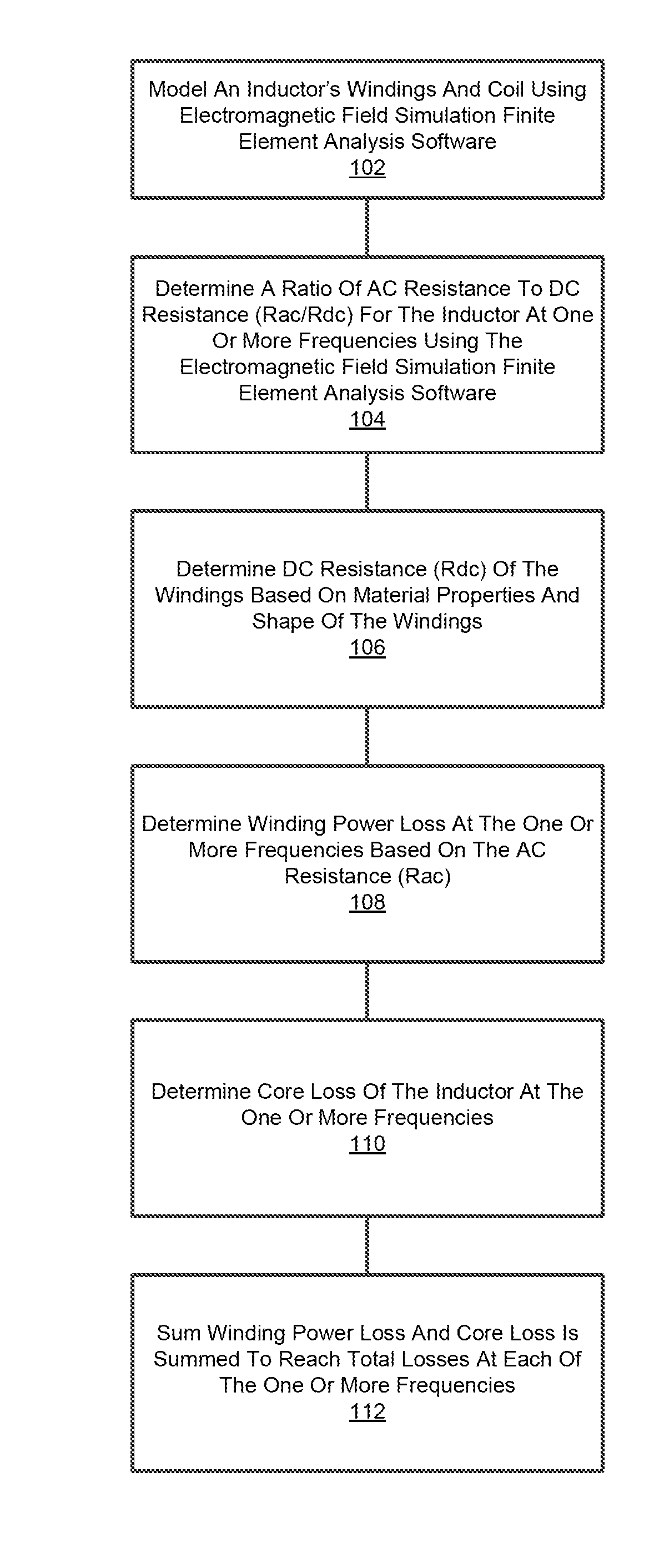
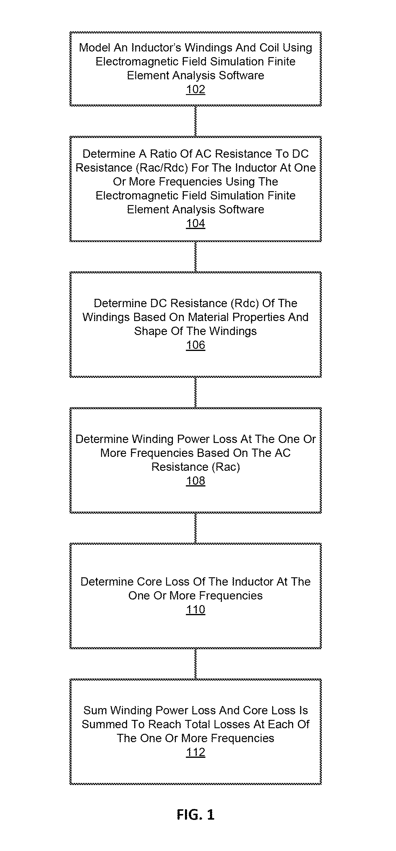
[0003]In general, embodiments of the present invention provide an improvement by, among other things, providing a method and system for determining power loss in an inductor. In accordance with one aspect, a method is provided of determining power loss in an inductor. The method comprises modeling an inductor's windings and core using electromagnetic field simulation finite element analysis software executing on a computer. A ratio of AC resistance to DC resistance (Rac / Rdc) for the inductor is determined at one or more frequencies using the electromagnetic field simulation finite element analysis software. DC resistance (Rdc) of the windings is determined based on material properties and shape of the windings. The DC resistance is used to determine AC resistance (Rac) using the ratio, Rac / Rdc. Winding power loss at the one or more frequencies is determined based on the AC resistance (Rac). Core loss of the inductor is determined at the one or more frequencies using a core loss versus frequency curve. Winding power loss and core loss are summed at each of the one or more frequencies to determine total power loss at the respective frequency.
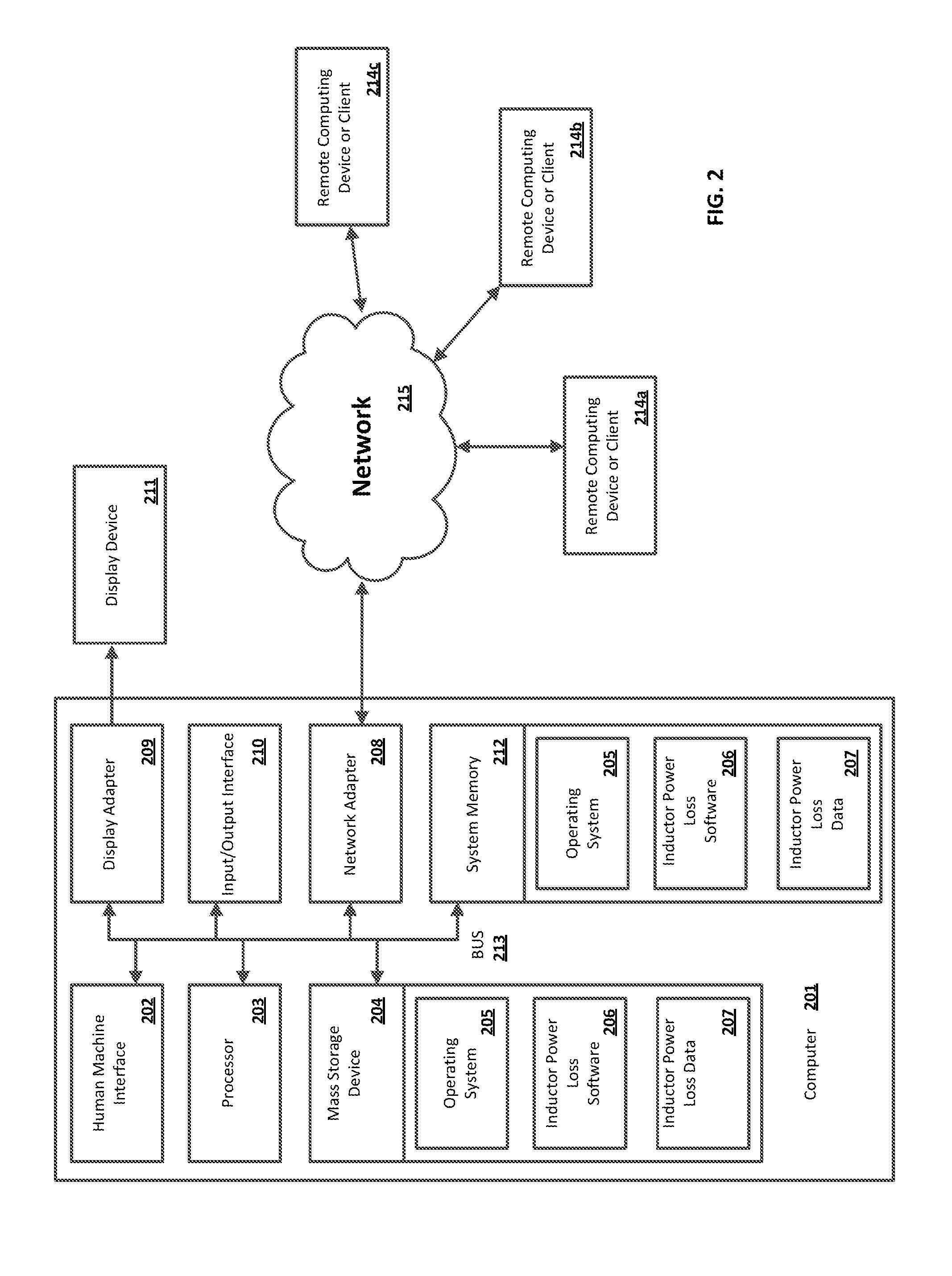
[0004]In accordance with another aspect, a system is provided for determining power loss in an inductor. In one embodiment, the system is comprised of a memory and a processor. The processor is operably connected with the memory. The processor is configured to model an inductor's windings and core using electromagnetic field simulation finite element analysis software stored in the memory and executed by the processor; determine a ratio of AC resistance to DC resistance (Rac / Rdc) for the inductor at one or more frequencies using the electromagnetic field simulation finite element analysis software; determine DC resistance (Rdc) of the windings based on material properties and shape of the windings, wherein the DC resistance is used to determine AC resistance (Rac) using the ratio, Rac / Rdc; determine winding power loss at the one or more frequencies based on the AC resistance (Rac); determine core loss of the inductor at the one or more frequencies using a core loss versus frequency curve stored in the memory; and sum, for each of the one or more frequencies, winding power loss and core loss.

Problems solved by technology

These non-fundamental frequencies can create challenges in designing an inductor.
(or 50 Hz.) designs to estimate the losses due to eddy currents, and therefore do not accurately predict the actual power loss.
Inductors built based on 60 Hz. or 50 Hz. designs that are exposed to frequencies that are above (or even below) 60 Hz. or 50 Hz. can have unexpectedly high losses and cause excessive heating of the induc

Method used


Image

  • Method and system for inductor power loss analysis
  • Method and system for inductor power loss analysis
  • Method and system for inductor power loss analysis

Examples


Embodiment Construction

[0009]Before the present methods and systems are disclosed and described, it is to be understood that the methods and systems are not limited to specific synthetic methods, specific components, or to particular compositions. It is also to be understood that the terminology used herein is for the purpose of describing particular embodiments only and is not intended to be limiting.

[0010]As used in the specification and the appended claims, the singular forms “a,”“an” and “the” include plural referents unless the context clearly dictates otherwise. Ranges may be expressed herein as from “about” one particular value, and / or to “about” another particular value. When such a range is expressed, another embodiment includes from the one particular value and / or to the other particular value. Similarly, when values are expressed as approximations, by use of the antecedent “about,” it will be understood that the particular value forms another embodiment. It will be further understood that the e...


PUM


Abstract

Described herein are embodiments of a method and system for determining power loss in an inductor. In accordance with one aspect, a method is provided of determining power loss in an inductor. The method comprises modeling an inductor's windings and core using electromagnetic field simulation finite element analysis software executing on a computer. A ratio of AC resistance to DC resistance (Rac / Rdc) for the inductor is determined at one or more frequencies using the electromagnetic field simulation finite element analysis software. DC resistance (Rdc) of the windings is determined based on material properties and shape of the windings. The DC resistance is used to determine AC resistance (Rac) using the ratio, Rac / Rdc. Winding power loss at the one or more frequencies is determined based on the AC resistance (Rac). Core loss of the inductor is determined at the one or more frequencies using a core loss versus frequency curve. Winding power loss and core loss are summed at each of the one or more frequencies to determine total power loss at the respective frequency.

Description

BACKGROUND OF THE INVENTION[0001]Switch mode power supplies and the use of solid-state power electronic devices that employ pulse-width modulation (PWM), as known to those of ordinary skill in the art, can cause frequencies on a power system well above and even below the fundamental power frequencies of 60 Hz. (U.S.) or 50 Hz (Europe). For example, solar inverters that employ PWM can impose frequencies from DC (0 Hz) up to over 100 KHz, sometimes with a combination of frequencies and waveshapes, such as a combination of a 60 Hz sine wave and also a 3 KHz triangle wave, that are seen by inductors associated with the device. These non-fundamental frequencies can create challenges in designing an inductor. For instance, purchasers of inductors generally prepare inductor specifications with high-level application requirements, such as inductance, current / frequency spectrum, power loss, etc. Actual detailed design of the inductors (core material, number of turns, size, etc.) was left up ...

Claims


Application Information

Patent Timeline
Patent Type & Authority Applications(United States)
IPC IPC(8): G06F17/10
CPCG06F17/5018H01F37/00G06F2217/78G06F17/5036G06F30/367G06F30/23G06F2119/06
Inventor WAGONER, ROBERT GREGORY
Owner GENERAL ELECTRIC CO
Learn More