
Digital Waveform Synthesis

a digital waveform and waveform technology, applied in the direction of trigometric functions, instruments, dc source parallel operation, etc., can solve the problem that sfdr is typically limited by limited outpu

Active Publication Date: 2012-03-01
INFINEON TECH AG
View PDF6 Cites 4 Cited by
  • Summary
  • Abstract
  • Description
  • Claims
  • Application Information

AI Technical Summary

Problems solved by technology

The SFDR is typically limited by limited output impedance of current sources used in the current cells of the waveform synthesizer.

Method used


Image

  • Digital Waveform Synthesis
  • Digital Waveform Synthesis
  • Digital Waveform Synthesis

Examples


Embodiment Construction

[0011]In the following, some embodiments of the present invention will be described in more detail and with reference to the accompanying drawings. It is to be understood that the following description is given only for the purpose of illustration and is not to be taken in a limiting sense. The scope of the invention is not intended to be limited by the embodiments as described hereinafter, but is intended to be limited only by the appended claims.

[0012]Further, it is to be understood that in the following description of embodiments any direct connection or coupling between functional blocks, devices, components, circuit elements or other physical or functional units as described or shown in the drawings could also be implemented by an indirect connection or coupling, i.e. a connection or coupling comprising one or more intervening elements. Furthermore, it should be appreciated that functional blocks or units shown in the drawings may be implemented as separate circuits, but may al...


PUM


Abstract

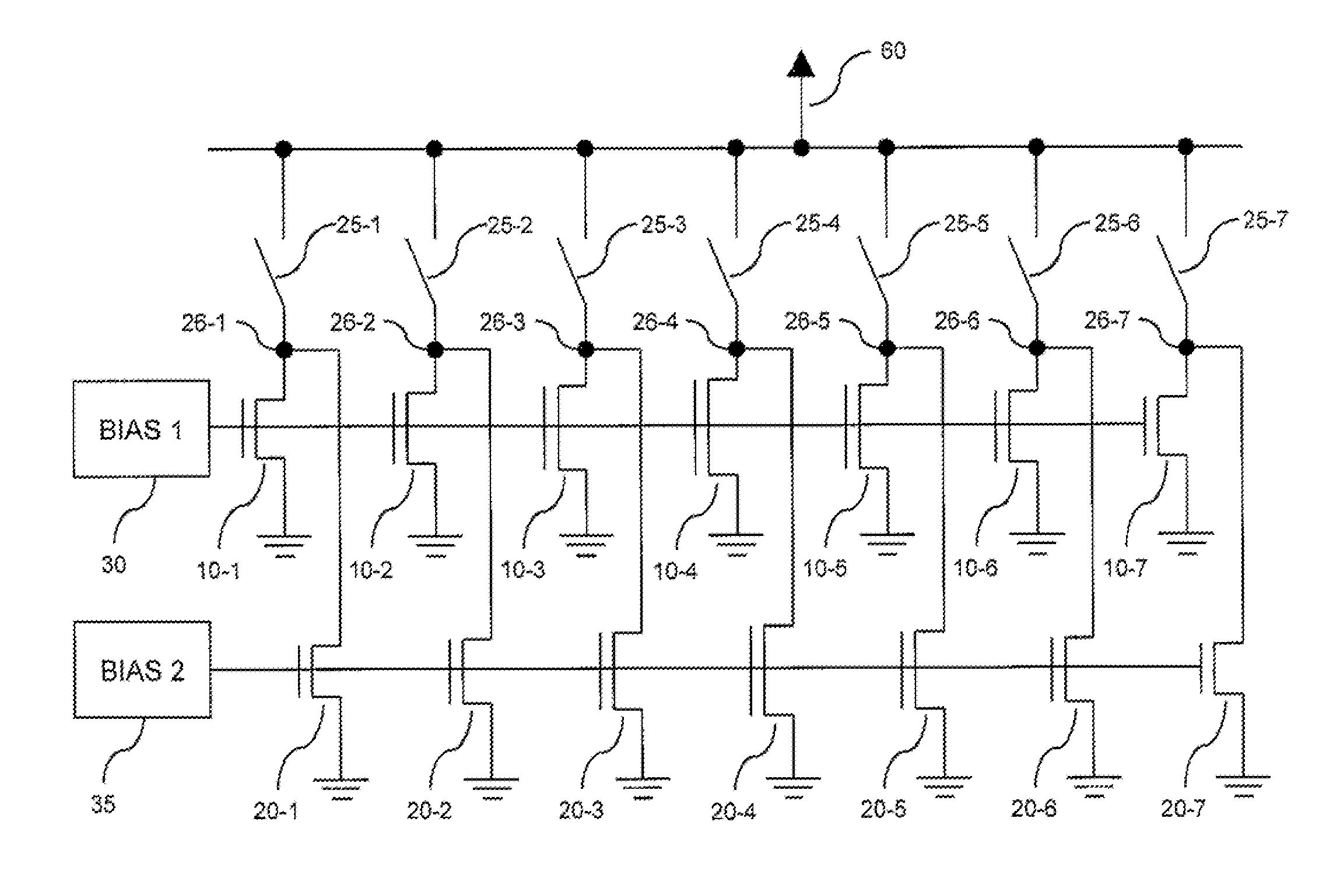
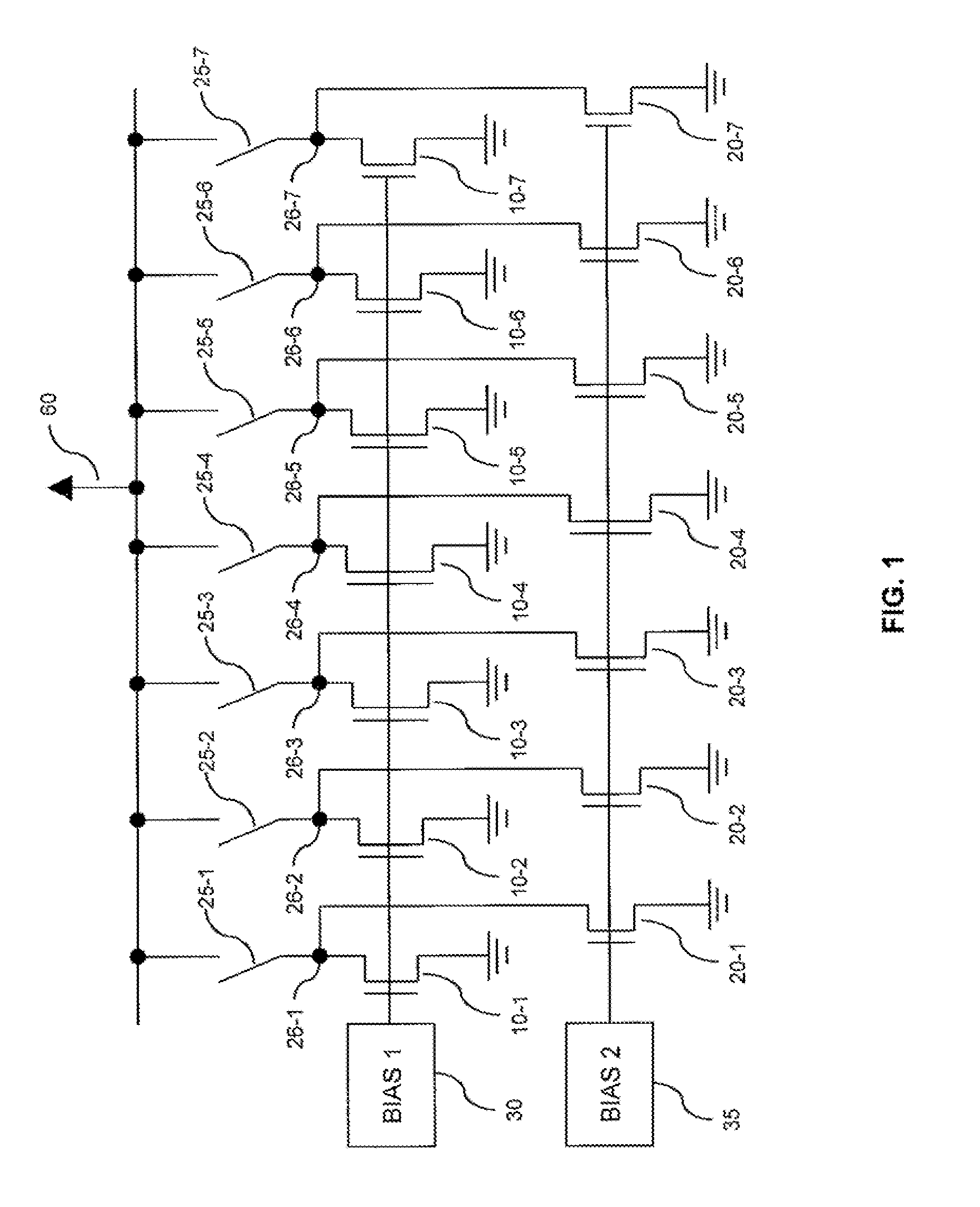
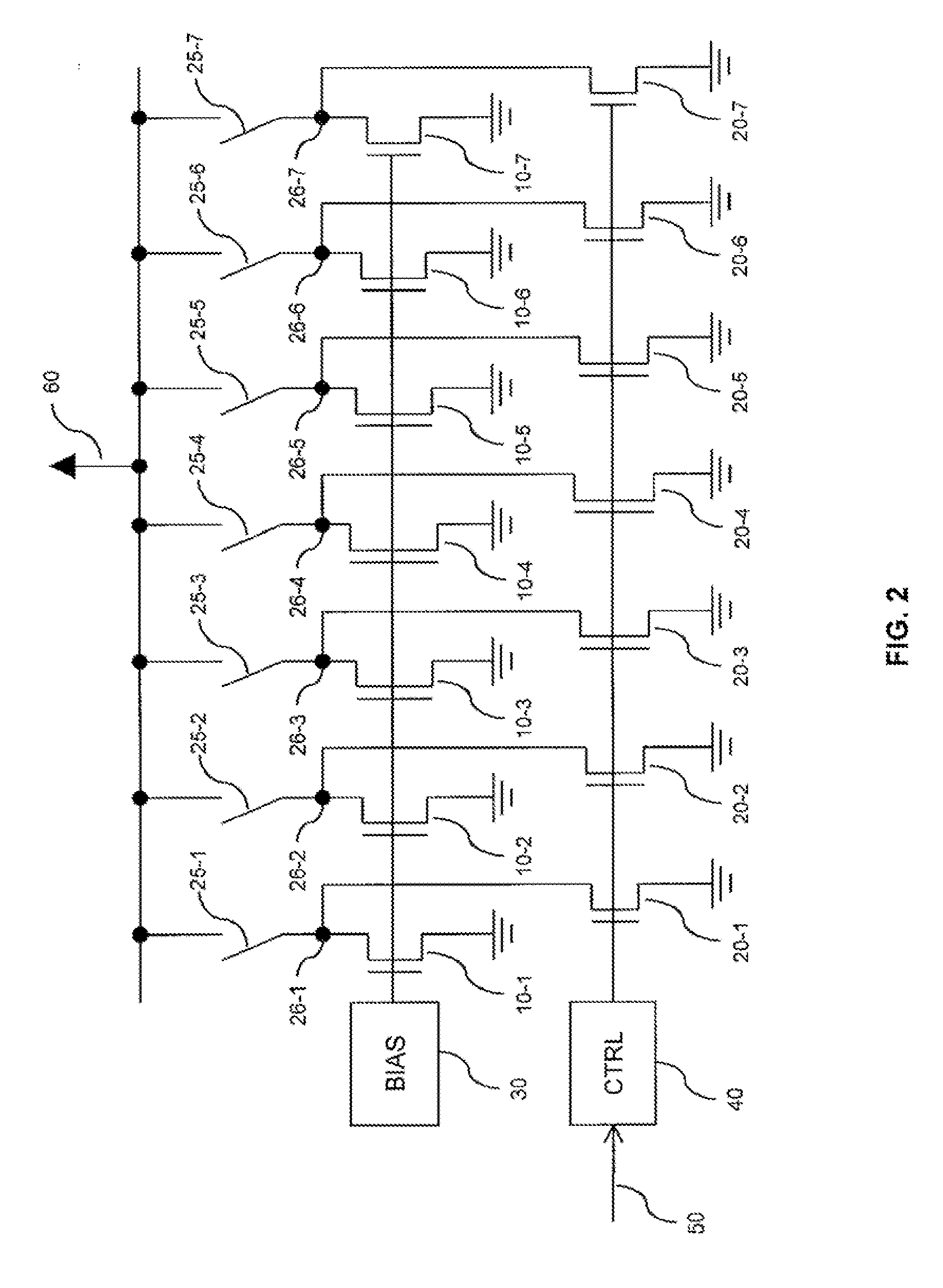
A circuit is provided with a plurality current cells. The current cells each comprise a main current source and an auxiliary current source coupled in parallel. The main current source supplies a main current to a current output of the current cell, and the auxiliary current source supplies an auxiliary current to the current output of the current cell. The main current sources are weighted according to a first predefined waveform, and the auxiliary current sources are weighted according to a second predefined waveform which is different from the first predefined waveform.

Description

FIELD OF THE INVENTION[0001]The present invention relates to circuits and methods for digital waveform synthesis.BACKGROUND OF THE INVENTION[0002]In synthesis of a sine waveform, it is known to use direct digital frequency synthesis by switching a number of weighted current cells on the basis of a digital code signal. The performance of a corresponding waveform synthesizer can be defined by the spurious-free dynamic range (SFDR) of the generated sine wave at a certain frequency. The SFDR is typically limited by limited output impedance of current sources used in the current cells of the waveform synthesizer. The effect of the limited output impedance is that, with increasing number of activated current cells, the output current of each current cell decreases from its nominal value. The output signal of the waveform synthesizer will therefore deviate from an ideal sine waveform.[0003]Accordingly, there is a need for techniques which allow for accurate digital waveform synthesis.BRIEF...

Claims


Application Information

Patent Timeline
IPC IPC(8): H03B28/00H02J4/00
CPCG06F2101/04G06F1/022
Inventor KUTTNER, FRANZFULDE, MICHAEL
Owner INFINEON TECH AG
Learn More