
Classifying apparatus, classifying method, toner and method for producing the toner

a technology of toner and classifier, which is applied in the direction of reverse direction vortex, instruments, developers, etc., can solve the problems of low classification efficiency of jet pulverizer, decreased classification accuracy, and decreased dispersion performance of conventional ds air classifying apparatuses, so as to improve classification efficiency and improve efficiency , the effect of smooth flow

Active Publication Date: 2012-03-01
RICOH KK
View PDF4 Cites 1 Cited by
  • Summary
  • Abstract
  • Description
  • Claims
  • Application Information

AI Technical Summary

Benefits of technology

[0116]Next, in addition to the relationship R1≧R2, numerical analysis was conducted for comparing the louver ring 6 satisfying the relationship α≧30° and the louver ring 6 satisfying the relationship α<30° with each other, where a denotes an angle between lines connecting the center of the louver ring 6 with both ends of each slat 5 of the louver ring 6. As a result, the difference between the maximum speed and the minimum speed was about 2 m / s as a result of extraction of the speeds of air flow passing through the gaps between the slats 5 when using the louver ring 6 satisfying the relationships α≧30° and R1≧R2. Thus, the difference of the maximum and minimum speeds could be decreased by about 2 m / s as compared with the difference therebetween when satisfying the relationship R1≧R2; i.e., about 4 m / s. Also, when using the louver ring 6 satisfying the relationships R1≧R2 and α<30°, the difference between the maximum speed and the minimum speed was about 5 m / s. This difference was greater by about 1 m / s than that obtained when satisfying the relationship R1≧R2, not showing advantageous effects. Thus, by satisfying the relationship α≧30°, the classification efficiency can be improved more than conventional cases. Note that the upper limit of α is about 65°.
[0117]Furthermore, in addition to the relationship R1≧R2, numerical analysis was conducted for comparing the louver ring 6 satisfying the relationship β≧15° and the louver ring 6 satisfying the relationship β<15° with each other, where β denotes an angle formed between a line connecting the center 19 of the louver ring 6 with the powder material feeding port's inner outlet 17 and a line connecting the center 19 of the louver ring 6 with the intersection point 18 which is formed by an extended line of the wall surface 2b of the powder material feeding port 2 at the side of the louver ring (i.e., a straight line connecting the powder material feeding port's inner inlet 16 with the powder material feeding port's inner outlet 17) and by a line that is in parallel with a line containing an opening 2a of the powder material feeding port 2 and that passes through the center 19 of the louver ring 6 (i.e., by a straight line that extends from the center 19 of the louver ring 6 in parallel with the feed opening 2a of the powder material feeding port 2). As a result, when using the louver ring 6 satisfying the relationships β≧15° and R1≧R2, the difference between the maximum speed and the minimum speed was about 3 m / s as a result of extraction of the speeds passing through the gaps between the slats 5 on the circumference. Thus, the difference of the maximum and minimum speeds could be decreased by about 1 m / s as compared with the difference therebetween when satisfying the relationship R1≧R2; i.e., 4 m / s. Also, when using the louver ring 6 satisfying the relationship R1≧R2 and the louver ring 6 satisfying the relationships R1≧R2 and β<15°, the difference between the maximum speed and the minimum speed was about 5 m / s in either case. This difference was greater by about 1 m / s than that obtained when satisfying the relationship R1≧R2, not showing advantageous effects. Thus, by satisfying the relationship β≧15°, the classification efficiency can be improved more than conventional cases. Note that the upper limit of β is about 45°.
[0118]Further, as illustrated in FIGS. 8A to 8D, the slats 5 constituting the louver ring 6 are made detachably mountable. FIGS. 8A to 8D are structural drawings each showing part of a detachment mechanism of the slats in relation to a state in which the slats have been detached from a respective classifying apparatus. In general, when a classifying apparatus is continuously operated to classify powder material, the powder material may adhere to the surfaces of the slats 5, although the extent depends upon classifying conditions and the type of the powder material. When the adherence of the powder material proceeds, cleaning at the time when the powder material is changed will be troublesome. Moreover, the gaps between the slats 5 are narrowed owing to the adherence of the powder material, thereby causing pressure loss. As a result, the fed air does not smoothly flow, the speed of the airflow in the classification chamber 7 decreases, and thus there may be a decrease in classification efficiency. Thus, by making the slats 5 detachably mountable, it is possible to simplify the operation of cleaning off the attached powder material and thereby reduce the time spent on the cleaning, so that the total amount of time required at the time of a change in conditions is shortened and thus it is possible to improve productivity.
[0119]Regarding the classifying apparatus and the classifying method of the present invention, it is possible to increase the classification efficiency by making a simple alteration to the louver ring 6 that is a component of the classifying apparatus and thus to highly efficiently classify particles of a desired diameter range with less error and favorable classification accuracy. Furthermore, the classifying apparatus and the classifying method of the present invention can be highly effectively applied to production of products in fine powder form which are some micrometers in particle diameter, for example, resins, agricultural chemicals, cosmetics and pigments. In particular, they are suitable for the method for producing a toner described below.(Method for Producing a Toner)
[0120]A method of the present invention for producing a toner includes at least a classifying step, preferably includes a melt-kneading step and a pulverizing step and, if necessary, includes other step(s).
[0121]The classifying step is performed using the above-described classifying apparatus of the present invention.<Melt-Kneading Step>

Problems solved by technology

Thus, the jet pulverizer is low in classification efficiency, which is problematic.
When used to disperse such increased number of particles, the dispersion performance of conventional DS air classifying apparatuses will decrease, resulting in decreased classification accuracy.
This inevitably leads to inclusion of coarse particles into a fine powder discharge region.
As a result, the product obtained by the classification process may cause background smear and improper transfer and may therefore lead to decreased image quality.
Also, such inclusion of coarse particles may also impose an excessive load on the classifier during the production process and may thus decrease the efficiency of classification as well as the energy efficiency of pulverization.
This configuration is disadvantageous in that when raw materials are fed with high-pressure air, the pressure difference within the dispersion chamber causes the raw materials to be released from the dispersion chamber into the atmosphere, making it difficult to further continue to conduct the classification process.
However, since part of the louver ring is located across an extended line of the louver ring side wall (i.e., an extended line of a straight line connecting a powder material feeding port's inner inlet and a powder material feeding port's inner outlet) (FIG. 5), in the above classifier, air flow fed from the powder material feeding port collide with the slats to potentially be slow in swirling speed.
In addition, as a result of the collision of the airflow with the slats, the airflow through the gaps between the slats is disturbed, and the speed of the airflow through the gaps therebetween is varied from place to place in the annually arranged slats.
Thus, the fed powder material is not sufficiently dispersed to potentially lead to a drop in classification accuracy and production yield, which is problematic.
However, this proposed technique poses a problem that the fed raw material cannot efficiently be dispersed since both of the raw material and the gas do not pass through the louver ring.

Method used


Image

  • Classifying apparatus, classifying method, toner and method for producing the toner
  • Classifying apparatus, classifying method, toner and method for producing the toner
  • Classifying apparatus, classifying method, toner and method for producing the toner

Examples


example 1

[0168]A powder material was classified with a classifying apparatus shown in FIG. 7 using a louver ring 6 set so as to satisfy the following: Distance R1=275 mm, Distance R2=260 mm, Angle α=25° and Angleβ=10°. In this louver ring, the thickness of each slat 5 was 4 mm and the number of slats 5 was 13. The obtained powder material was found to have a volume average particle diameter of 4.7 μm (measured according to the Coulter Counter method) and to contain coarse particles having a particle diameter of 8.0 μm or more in an amount of 1.6% by mass. The amount of the powder material processed per hour; i.e., feed amount, was found to be 80 kg / h.

example 2

[0169]A powder material was classified under the same conditions and with the same apparatus as in Example 1, except that the louver ring was changed to a louver ring 6 set so as to satisfy the following: R1=275 mm, R2=260 mm, α=30° and β=10°. The obtained powder material was found to have a volume average particle diameter of 4.7 μm (measured according to the Coulter Counter method) and to contain coarse particles having a particle diameter of 8.0 μm or more in an amount of 1.5% by mass. The amount of the powder material processed per hour; i.e., feed amount, was found to be 82 kg / h.

example 3

[0170]A powder material was classified under the same conditions and with the same apparatus as in Example 1, except that the louver ring was changed to a louver ring 6 set so as to satisfy the following: R1=275 mm, R2=260 mm, α=25° and β=15°. The obtained powder material was found to have a volume average particle diameter of 4.7 μm (measured according to the Coulter Counter method) and to contain coarse particles having a particle diameter of 8.0 μm or more in an amount of 1.6% by mass. The amount of the powder material processed per hour; i.e., feed amount, was found to be 83 kg / h.


PUM


Abstract

A classifying apparatus including a cylindrical casing, a powder material feeding port, a louver ring disposed in the casing to be in communication with the powder material feeding port in a horizontal direction, a center core, a separator core, a dispersion chamber defined by the center core and an inner wall of the casing at the powder material-fed side, a classification chamber defined by the center core, the separator core and a side inner wall of the casing, and a flow path encircling the louver ring, wherein in a horizontal cross section of part of the classifying apparatus where the part contains the powder material feeding port and the louver ring, the louver ring is located at a position where the louver ring does not intersect with an extended line of a wall surface of the powder material feeding port at the side of the louver ring.

Description

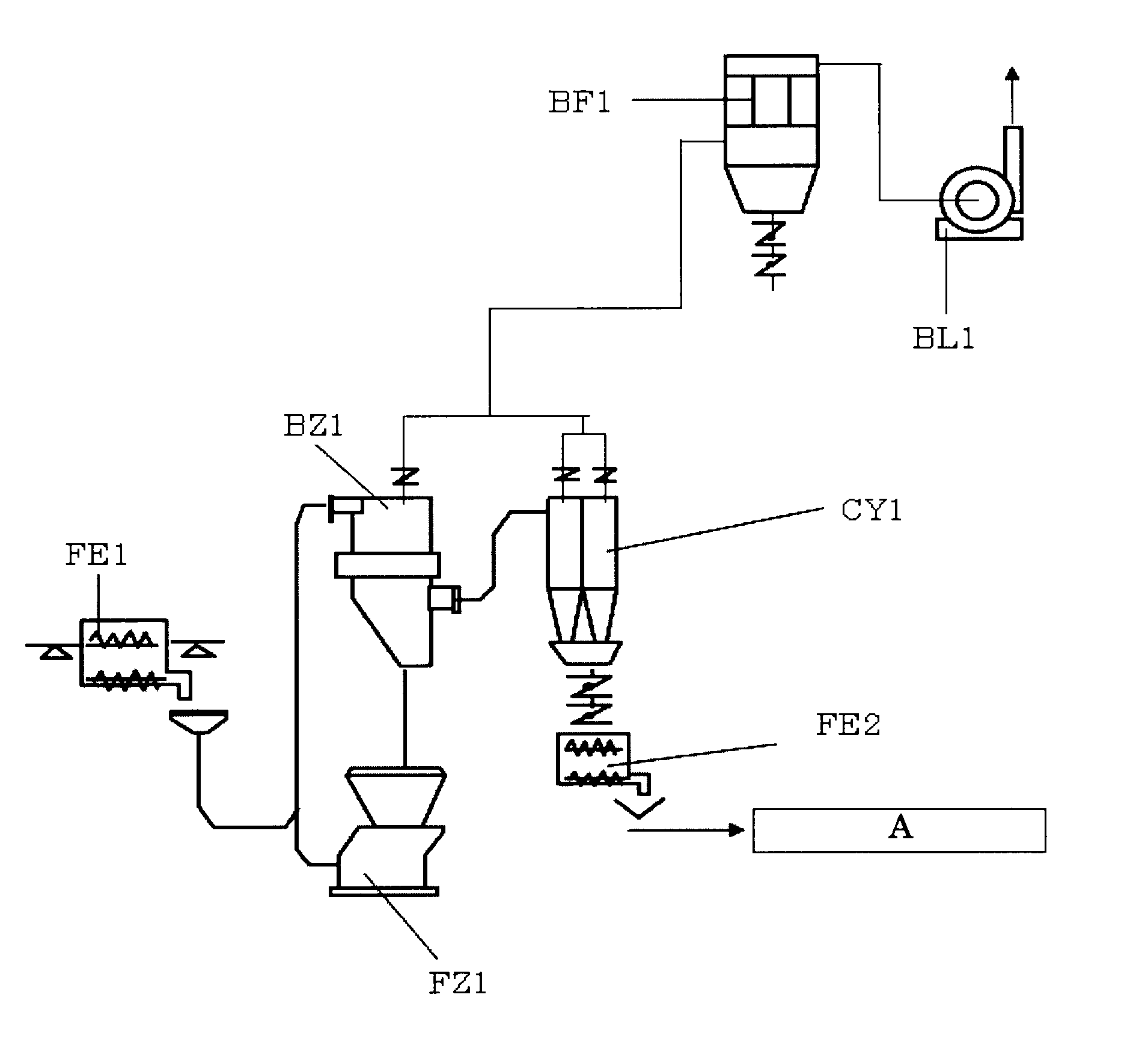
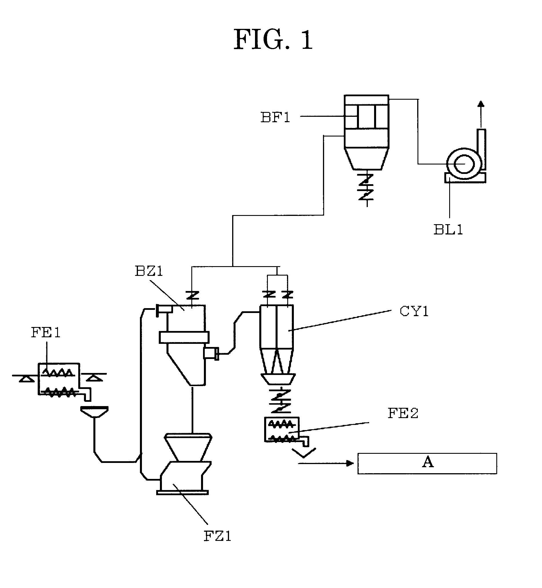
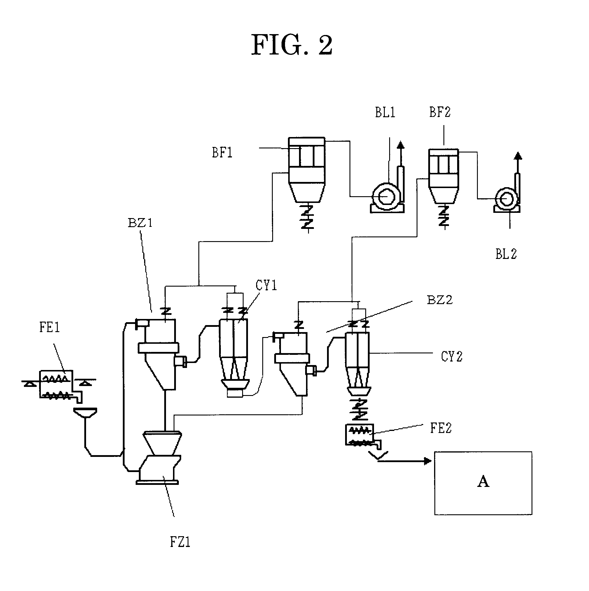
BACKGROUND OF THE INVENTION[0001]1. Field of the Invention[0002]The present invention relates to a classifying apparatus and a classifying method which are used to produce dry toner for developing electrostatic images in electrophotography, electrostatic recording, electrostatic printing, etc.; and to a toner and a method for producing the toner.[0003]2. Description of the Related Art[0004]Several traditional approaches are known for classifying pulverized coarse toner particles: a combination of a single classifier BZ1 and a single pulverizer FZ1 (as shown in FIG. 1, for example); a combination of two classifiers BZ1 and BZ2 and a single pulverizer FZ1 (as shown in FIG. 2, for example); and a combination of two classifiers BZ1 and BZ2 and two pulverizers FZ1 and FZ2 (as shown in FIG. 3, for example). Note that, in FIGS. 1 to 3, reference character A denotes a fine powder-classifying unit (step).[0005]One type of the pulverizers used in these systems is a jet pulverizer that propels...

Claims


Application Information

Patent Timeline
Patent Type & Authority Applications(United States)
IPC IPC(8): B04C3/00
CPCG03G9/0817
Inventor MATSUSHITA, NATSUKOTANAKA, TETSUYAMAKINO, NOBUYASU
Owner RICOH KK
Learn More