Nerve stimulator measuring device
a nerve stimulator and measuring device technology, applied in the field of nerve stimulator measuring devices, can solve the problems of inaccurate readings, time-consuming and labor-intensive, etc., and achieve the effect of determining the proper position quickly and easily
- Summary
- Abstract
- Description
- Claims
- Application Information
AI Technical Summary
Benefits of technology
Problems solved by technology
Method used
Image
Examples
first embodiment
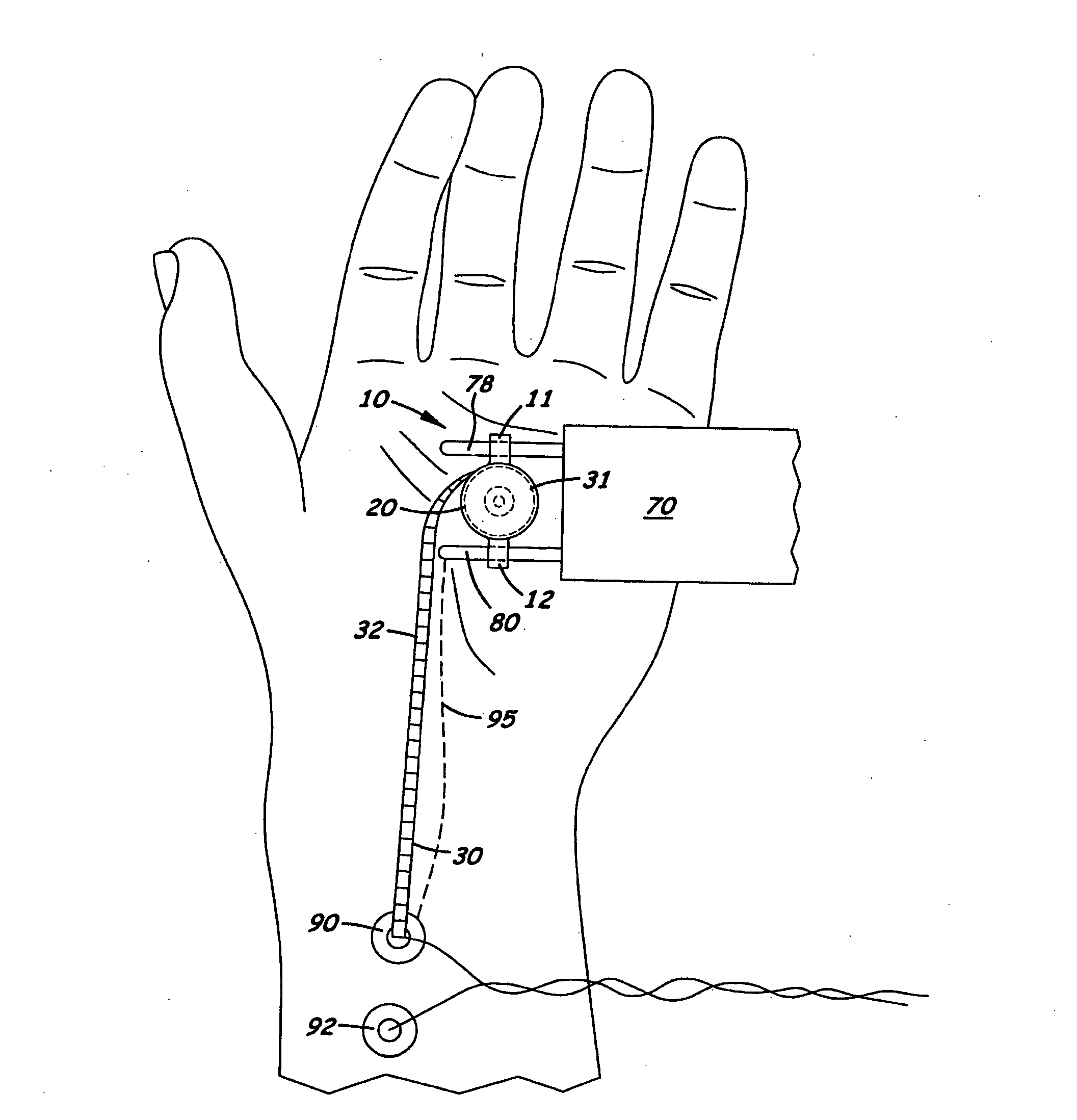
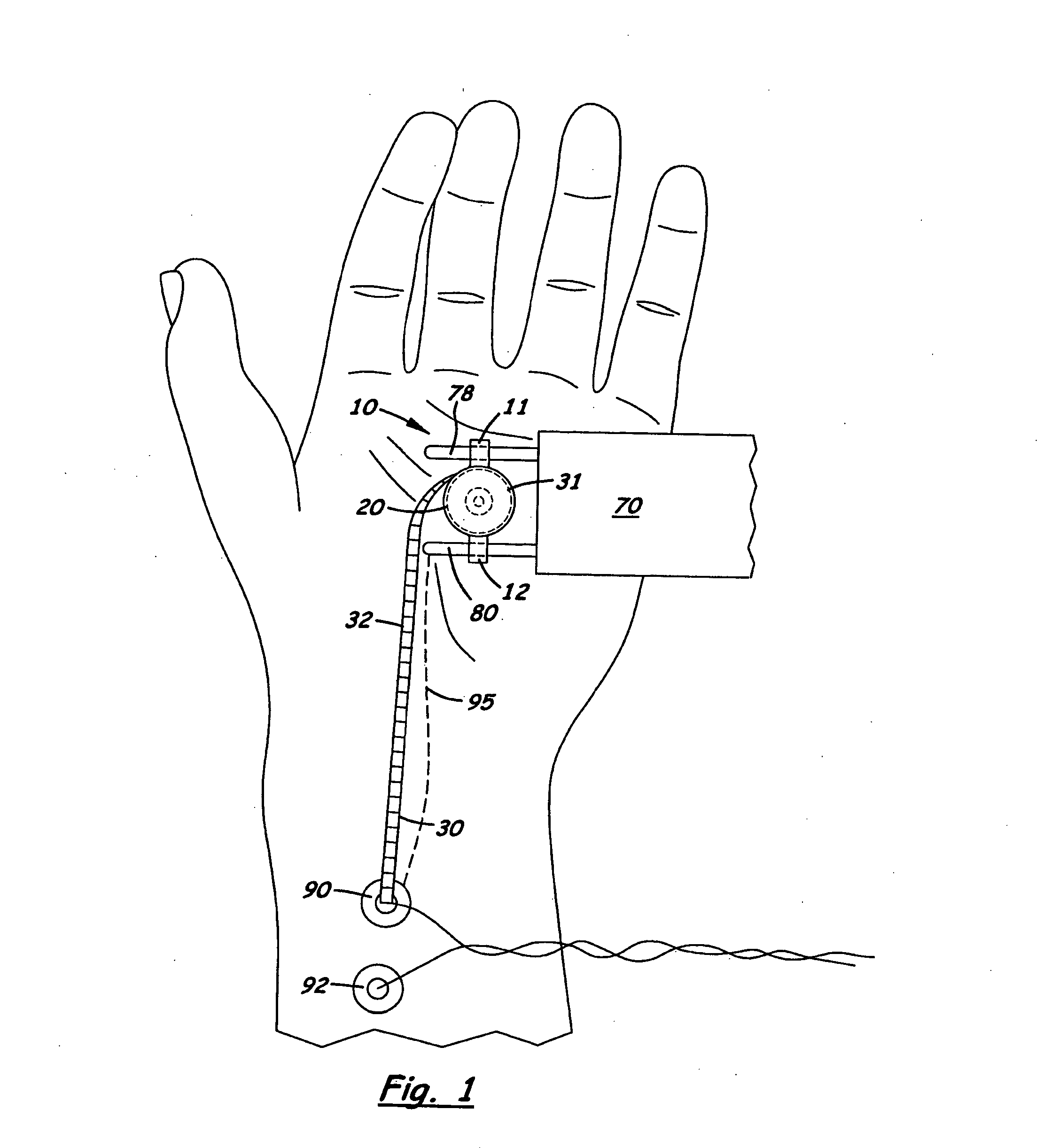
[0044]Shown in the accompanying FIGS. 1-26 are six embodiments of an electrical nerve stimulator measuring device used to measure the distance of conductivity in a peripheral nerve. Referring to the first embodiment shown in FIGS. 1, 3, and 4, the device 10 comprises an outer housing 20 with two side ears 11, 12 that attach to the anode and cathode probes 78, 80, respectively, on a handheld electrical nerve stimulator 70.
[0045]Located inside the outer housing 20 is a retractable spool 31 with a flexible tape 30 with length measure units 32 printed thereon. In the preferred embodiment, the two ears 11, 12 include two bores 24, 26 designed to slidingly receive the anode and cathode probes, 78, 80 respectively. The outer housing 20 is aligned on the probes 78, 80 so that the tape measure 30 unwinds around a center axis that is perpendicular to the longitudinal axis of the two probes 78, 80.
second embodiment
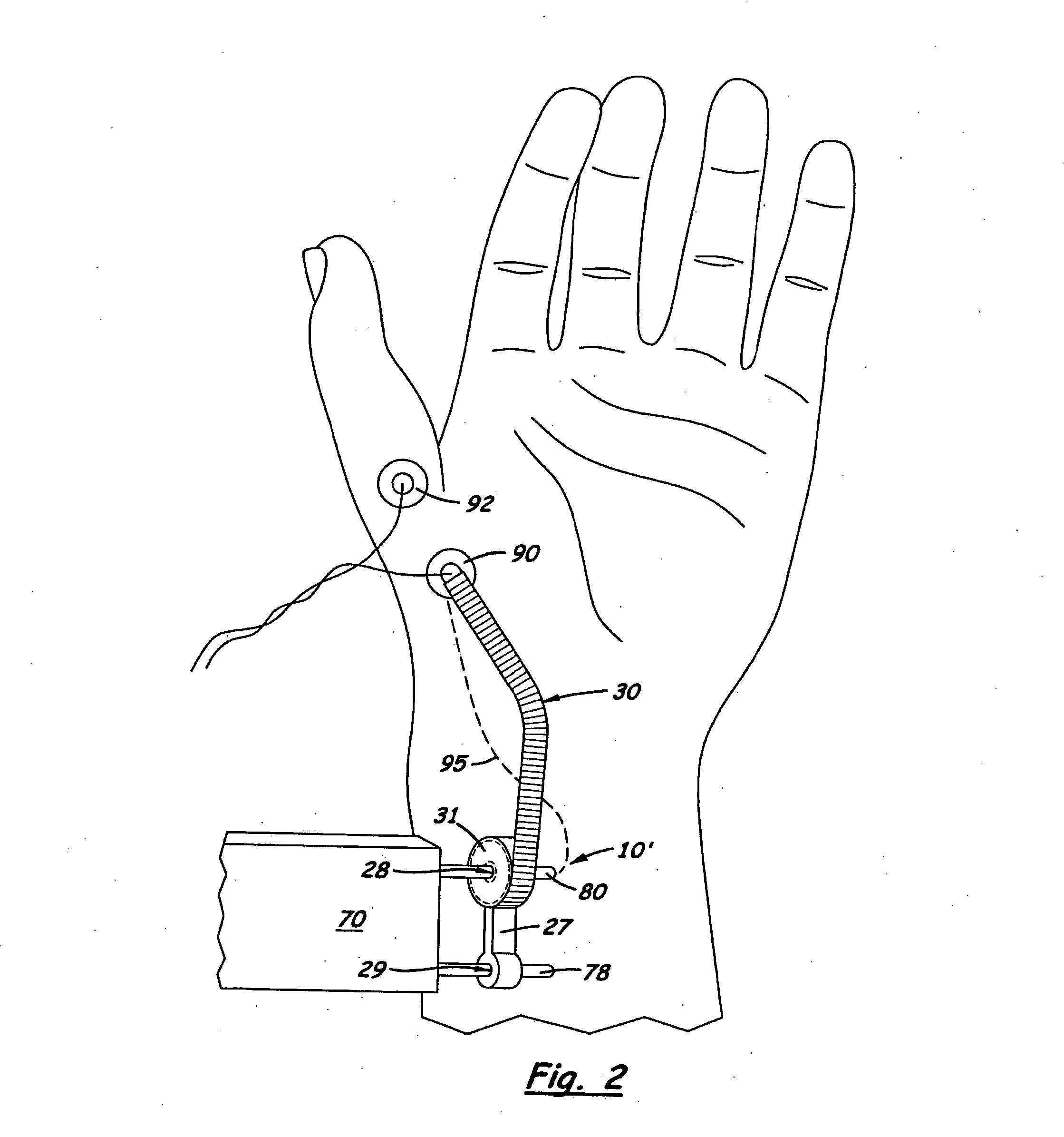
[0046]the device 10′, shown in FIGS. 2, 5 and 6, comprises the tape measure 30 also disposed inside an outer housing 20′ designed to be coaxially aligned around the cathode probe 80. The outer housing 20′ includes a center bore 28 that receives the cathode probe 80 on the electrical nerve stimulator 70. A portion 27 of the outer housing 20′ extends laterally and includes a second bore 29 designed to slidingly receive the anode probe 78. The spool 31 for the tape measure 30 is aligned inside the outer housing 20′ so that it unwinds around a center axis coaxially aligned with the cathode probe 80. When properly assembled on the electrical nerve stimulator 70, the anode probe 78 extends through the second bore 29 and prevents the outer housing 20′ from rotating on the stimulator 70.
third embodiment
[0047]FIGS. 7 and 8 show the measuring device, denoted 10″, design to be used with an electro-magnetic nerve stimulator 85. Device 10″ comprises two clamping members 86, 87 located on the opposite sides of a cylindrical shaped outer housing 20″. Like the first two embodiments, located inside the outer housing 20″ is a retractable spool 31 with a flexible tape measure 30 wound thereon. Formed on the side of the outer housing 20″ is an exit port 88 through which the distal end of the tape measures 30 extends. The two clamping members 86, 87 are designed to extend and adjustably squeeze around the circular body of the electrical nerve stimulator 85. A threaded bolt 100 and nut 99 are used to apply a clamping force to the two clamping members 86, 87. The outer housing 20 is aligned on the two clamping members 86, 87 to that its center axis is perpendicular to the longitudinal axis on the two clamping members 86, 87. When properly assembled, the exit port 88 is aligned over the center ax...
PUM
 Abstract
Description
Claims
Application Information
 - R&D
- Intellectual Property
- Life Sciences
- Materials
- Tech Scout
- Unparalleled Data Quality
- Higher Quality Content
- 60% Fewer Hallucinations
Browse by: Latest US Patents, China's latest patents, Technical Efficacy Thesaurus, Application Domain, Technology Topic, Popular Technical Reports.
© 2025 PatSnap. All rights reserved.Legal|Privacy policy|Modern Slavery Act Transparency Statement|Sitemap|About US| Contact US: help@patsnap.com


