
Connector element for a communication system and communication bus systems

a technology of communication system and connector element, applied in the field of connector element, can solve the problems of increasing the conductor length of the conducting elements of the bus structure, and achieve the effects of reducing the large number of variants, avoiding the mix-up of connector elements, and reducing material costs

Inactive Publication Date: 2012-02-16
ROBERT BOSCH GMBH
View PDF6 Cites 2 Cited by
  • Summary
  • Abstract
  • Description
  • Claims
  • Application Information

AI Technical Summary

Benefits of technology

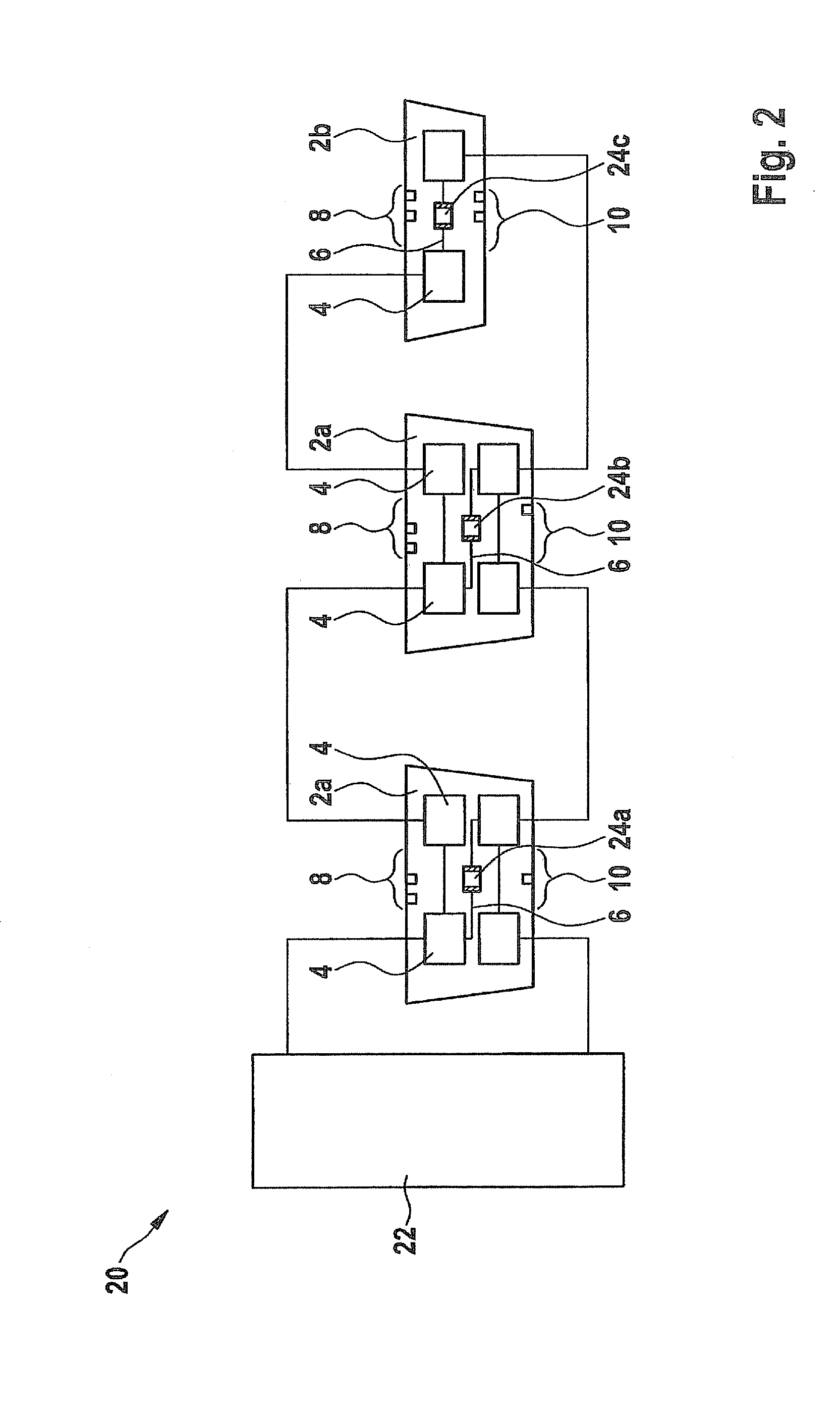
[0018]In the connector element according to the present invention, it may in particular be unnecessary to provide an option for looping through on a control unit, i.e., provision of a daisy chain. This may make it possible to save at least two contact elements or pins per sensor; furthermore, material cost is reduced in the control unit plug connector and in the printed board surface. This may result in a standardization of control units by reducing the large number of variants, since no differentiation is necessary in particular in equipping the control unit or in the bus network topology.
[0019]It may be possible to avoid providing terminating resistors which may possibly not be needed in individual elements, since they are positioned as an intermediate piece and not as an end piece, this also resulting in reducing the necessary printed board surface, making possible an optimization in the plug connector area.
[0020]In particular, a visual or optical encoding in an optically visible plug connector area may be used as a distinguishing feature, for example, in a service case in order to be able to exchange a defective device for a replacement device quickly without, for example, having to inspect the device for conclusively determining the type of device.
[0021]This results in error avoidance, for example, by connecting a wrong connector element, due to a biuniqueness of the connection between the terminal element, connector element or sensor element and the communication matrix according to a key and lock principle. A message catalog including the relevant transmitters and receiver is understood in particular to be a communication matrix. This may also make it possible to implement a standardization of a connection to a cable harness for connector elements, which may also ensure simple interchangeability. The use of plugs in the connector element, which are specifically adapted to or standardized for individual bus systems, i.e., the communication bus system contact elements, may be necessary or preferred.
[0024]A counterpart which is configured for accommodating the connector element may have a counterpart for the configuration bar, which may likewise be configured accordingly, for example mechanically. The encoding of the connector element, for example, via raises or indentations of the configuration bar, makes it possible to ensure that a corresponding connector element may be attached exclusively to the particular counterpart or receiving element which is configured for responding to the connector element. Likewise it may be ensured that only a matching or desired connector element may be attached at a specific position in a vehicle.
[0027]The configuration bars thus make it possible to obtain a biunique assignment of the connector element to the sensor element type, communication type and end piece and intermediate piece.

Problems solved by technology

This may, however, simultaneously result in an increase of a conductor length of the conducting elements of a bus structure.

Method used


Image

  • Connector element for a communication system and communication bus systems
  • Connector element for a communication system and communication bus systems
  • Connector element for a communication system and communication bus systems

Examples


Embodiment Construction

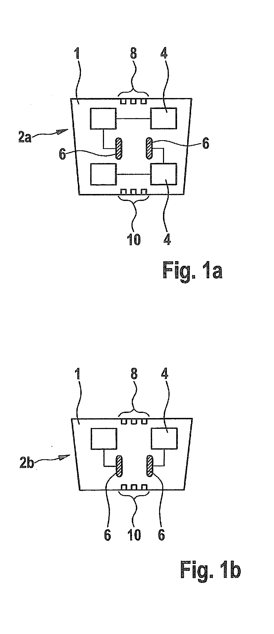
[0032]FIGS. 1a and 1b show an exemplary specific embodiment of an intermediate piece and an end piece according to the present invention.

[0033]FIG. 1a shows intermediate piece 2a. Intermediate piece 2a has, for example, a total of four communication bus system contact elements 4 and two internal terminal elements 6.

[0034]Two communication bus system contact elements 4 are in each case directly connected to one another and thus implement a daisy chaining or a looping through within intermediate piece 2a.

[0035]Communication bus system contact elements 4 may be implemented by standardized connecting elements such as pins or contact springs, which are situated, for example, on one surface of a housing 1 projecting to the outside. Internal terminal elements 6 make it possible to connect a sensor element, for example.

[0036]Furthermore, configuration bars 8, 10 are applied to the surface of housing 1. Configuration bars 8, 10 may in this case be implemented purely optically, for example, ...


PUM


Abstract

A connector element for assembling a communication system, having a plurality of communication bus system contact elements for connecting to a communication bus system, a plurality of internal terminal elements and a configuration encoding unit. The connector element is designed for assembling the communication bus system.

Description

FIELD OF THE INVENTION[0001]The present invention is directed to a connector element for assembling a communication system as well as a communication bus system.BACKGROUND INFORMATION[0002]An electrical / electronic architecture (E / E architecture) describes the structure of a vehicle electrical and electronic system, for example, in a passenger car or truck.[0003]Present-day E / E architectures connect, for example, control units and sensors in a motor vehicle and make it possible for various electronic components in a vehicle to communicate. A bus connection or a communication bus structure connects individual elements of the communication system which ultimately access the common bus and communicate with one another using the common bus.[0004]However, conventional bus structures may need, for example, a splice in a cable harness or control unit coupling elements, for example, control unit pins, for making possible an electrically conductive connection or coupling to the bus and accord...

Claims


Application Information

Patent Timeline
IPC IPC(8): G06F13/14
CPCH04L12/40032
Inventor SCHIER, JOHANNESKORNHAAS, ROBERT
Owner ROBERT BOSCH GMBH
Learn More