
Two-part endoscope surgical device

Inactive Publication Date: 2012-02-16
M S T MEDICAL SURGERY TECH
View PDF4 Cites 79 Cited by
  • Summary
  • Abstract
  • Description
  • Claims
  • Application Information

AI Technical Summary

Benefits of technology

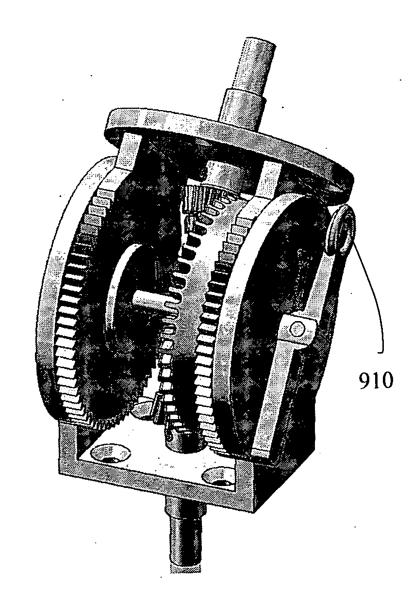
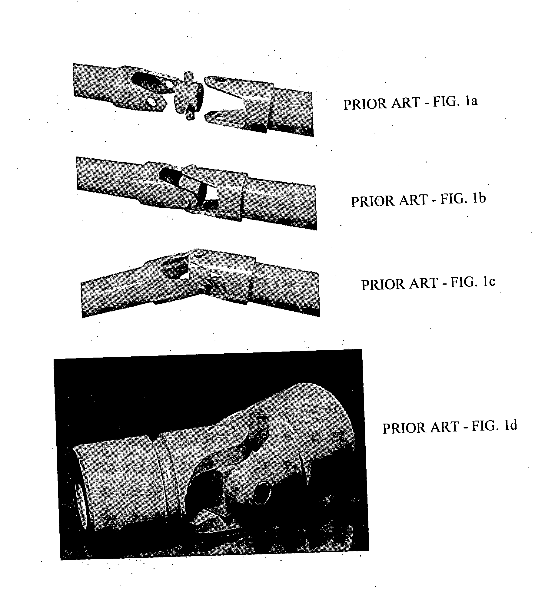
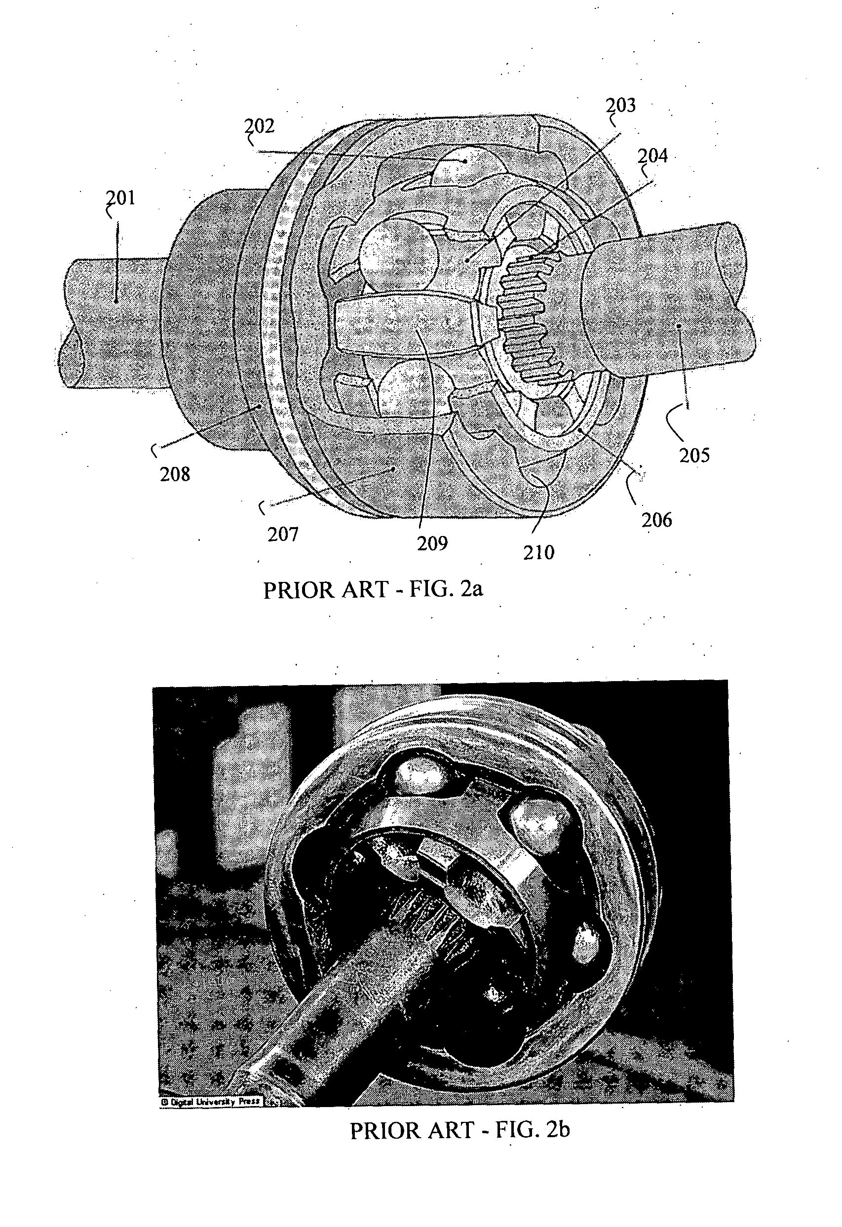
[0054]It is an object of the invention to provide a laparoscope composed of a set of detachable parts. A base unit attaches to a fixed location such as the floor, the side of an operating table, or the like. A body unit attaches to this base unit and is provided with a laparoscope and associated devices, such as surgical tools, camera, fiber optics, light sources, and the like. The body unit attaches easily to the base unit and is supported by it during surgery. It may be detached and replaced with another body unit suitable for different procedures. The device utilizes a novel torque-transmitting joint that allows a large number of degrees of freedom to be transmitted while allowing the several sections of the device to be rotated and translated through additional degrees of freedom. In this way a simple and modular means for performing a wide variety of surgical procedures is attained.
[0125]The device of the present invention has many technological advantages, among them simplification of the communication interface between surgeon and automated assistants; seamless interaction with conventional computerized automated endoscope systems; simplicity of construction; reliability; and user-friendliness. Additional features and advantages of the invention will become apparent from the following drawings and description.

Problems solved by technology

This gantry is often a somewhat cumbersome apparatus and is in general associated with a particular laparoscopic device.
The main disadvantage of the above interfaces is that they are based on cumbersome operations for starting and stopping movement directions that requires the surgeon's constant attention.
Arshak states in the article that other methods such as time of arrival, time differences of arrival and angle of arrival are not feasible in dense, multipath environments.
If, however, the transmission power is unknown, unstable or inaccurate, or if the propagation factor is unknown, then Arshak's method cannot be used.
These technologies still fail to address another complicating interface aspect of laparoscopic surgery, however, as they do not allow the surgeon to signal both to the automated assistant and to surgical colleagues on which surgical instrument his attention is focused.

Method used


Image

  • Two-part endoscope surgical device
  • Two-part endoscope surgical device
  • Two-part endoscope surgical device

Examples


embodiment 420

[0260]Reference is now made to FIG. 34, which illustrates an additional embodiment 420 of the invention herein disclosed. Surgical device 4201 is held in position by robot end effector, which comprises a plurality of shaft tubes 4204 (in the embodiment illustrated, there are 5 shaft tubes 4204a-4204e) connected in series by a set of joints 4205. One of said joints (in the embodiment shown, 4205a) connects the first shaft tube 4204a to the body of the instrument, while another (in the embodiment shown, 4206) is attached the final shaft tube (in the embodiment shown, 4204e) and comprises means (e.g. a closeable slot or hole) to hold the surgical device in a position fixed relative to the final shaft tube. Motor means for effecting movement of the shaft tubes is contained within motor box 4202, and the controller mechanisms are contained with controller box 4203.

embodiment 430

[0261]Reference is now made to FIG. 35, which illustrates the various DOF and an external view of the means for connecting medical device 4300 to the control unit according to an embodiment 430 of the invention. According to this embodiment, 6 independent DOF are available to the medical device (FIG. 35a): (1) rotation 4311 of the entire connecting means about the z-axis; (2) translation 4312 of the medical device along a predetermined axis within the x-y plane; (3) rotation 4313 of the medical device about the axis defined by 4312; (4) rotation 4314 of the medical device about an axis perpendicular to that defined by 4312; (5) rotation 4315 of the medical device about the z-axis; and (6) translation 4316 of the instrument along the z-axis. Motion about DOF 4312-4316 is accomplished without gross movement of the entire connecting means. As described in detail below, independent motions along these DOF are enabled by a system of n joints 4301 (in the embodiment shown, n=3; in other e...


PUM


Abstract

The present invention provides a two-part robotic device for positioning of a hand tool, comprising: a. a fixed base unit constantly fix to its position; b. a detachable body unit reversibly coupled to said fixed base unit, coupled to said current medical instrument; wherein said fixed base unit is adapted to provide independent movement to said hand tool, said independent movement selected from the group consisting of rotation and translation, and further wherein said detachable body unit is removable and replaceable from said fixed base unit such that upon exchange of said hand tool for a second hand tool, said second hand tool is placed in substantially the same location as the location of said hand tool prior to said exchange.

Description

FIELD OF THE INVENTION[0001]The present invention relates to a method and apparatus for laparoscopic surgery using a two-part device composed of a base unit and a detachable body unit. The invention furthermore relates to the guiding of such laparoscopic instruments and procedures, and in particular to interfaces that allow identification of the spatial position of a laparoscope during endoscopic surgery.BACKGROUND OF THE INVENTION[0002]In laparoscopic surgery, the surgeon performs the operation through one or more small incisions using long instruments, while observing the internal anatomy with an endoscope camera. The laparoscope is often provided with some form of gantry or holding unit to hold the external portion of the device in place. This gantry is often a somewhat cumbersome apparatus and is in general associated with a particular laparoscopic device. Each form of surgical laparoscope will have its own gantry which must be installed before use.[0003]For example U.S. Pat. No...

Claims


Application Information

Patent Timeline
IPC IPC(8): A61B1/00
CPCA61B1/00128A61B1/00149A61B19/2203A61B2019/5251A61B2019/266A61B2019/448A61B19/26A61B90/50A61B34/30A61B2090/508A61B90/98A61B2034/2051A61B1/313
Inventor SHOLEV, MORDEHAI
Owner M S T MEDICAL SURGERY TECH
Learn More