
Producing, Capturing and Using Visual Identification Tags for Moving Objects

a technology for visual identification and objects, applied in instruments, sensing record carriers, computing, etc., can solve the problems of two-dimensional barcodes or matrix codes, difficult to read, and only a relatively limited amount of information

Active Publication Date: 2012-02-16
RUJAN ENTWICKLUNG & FORSCHUNG
View PDF2 Cites 60 Cited by
  • Summary
  • Abstract
  • Description
  • Claims
  • Application Information

AI Technical Summary

Benefits of technology

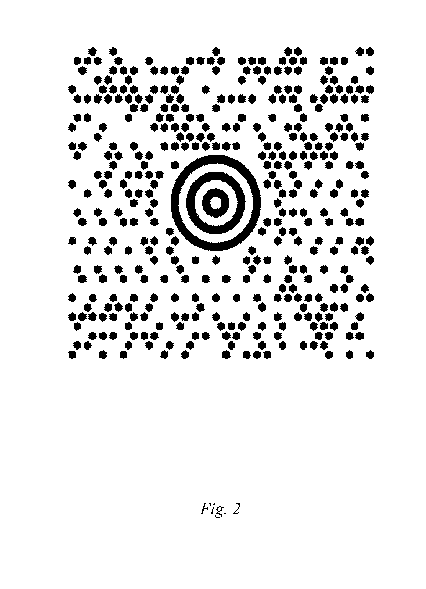
"This patent describes a way to use standard digital cameras to identify objects using visual reference tags. These tags consist of a central hexagon surrounded by layers of regular hexagons that are colored based on the optical spectrum of the camera. The tag design uses a new probabilistic signal decoding strategy based on parallel multi-scale frequency counts, which allows for accurate identification and decoding of the tag in one pass through the image. The invention also provides methods for producing and using these tags, which can be printed on standard color printers and are highly aesthetic. The technical effects of this patent include ubiquitous augmented reality, improved visual identification of objects, and a new method for generating and decoding visual reference tags."

Problems solved by technology

A problem associated with bar codes is that they are difficult to read at a distance, and can hold only a rather limited amount of information.
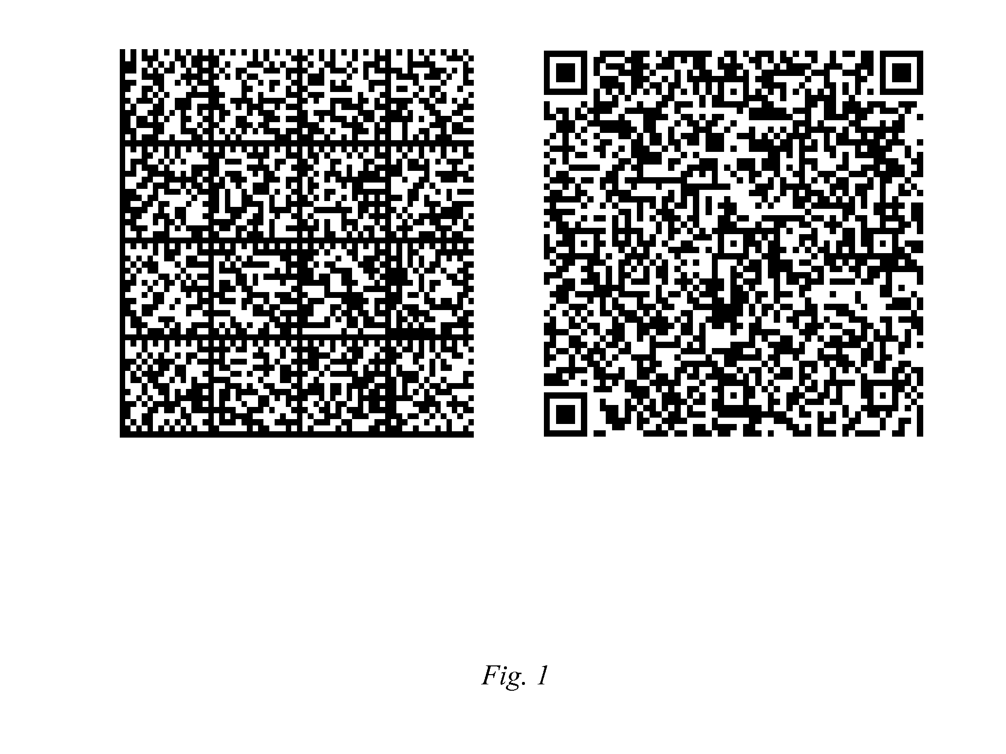
Two-dimensional barcodes or matrix codes contain a greater amount of information but are even more difficult to read and align.
Capturing known 2D matrix codes with a low resolution digital camera fails under changing illumination conditions or when the target is too distant.
None of these codes is able to identify reliably a variable number of tags present at the same time in a moving camera's visual field.
The storage capacity of the disclosed type of visual reference tags is necessarily restricted by the fact that the tags must be relatively large, so that they can be captured reliably from a distance and in arbitrary rotational position.
RFID tags and in particular their support systems are quite expensive and are often used for controlling or monitoring purposes.
Name tags and visit cards are difficult to read reliably by mobile devices, partly because optical character recognition (OCR) uses computational resources heavily.
Using RFID's, smart cards, and similar electronic devices requires additional equipment and might be considered privacy intrusive.

Method used


Image

  • Producing, Capturing and Using Visual Identification Tags for Moving Objects
  • Producing, Capturing and Using Visual Identification Tags for Moving Objects
  • Producing, Capturing and Using Visual Identification Tags for Moving Objects

Examples


Embodiment Construction

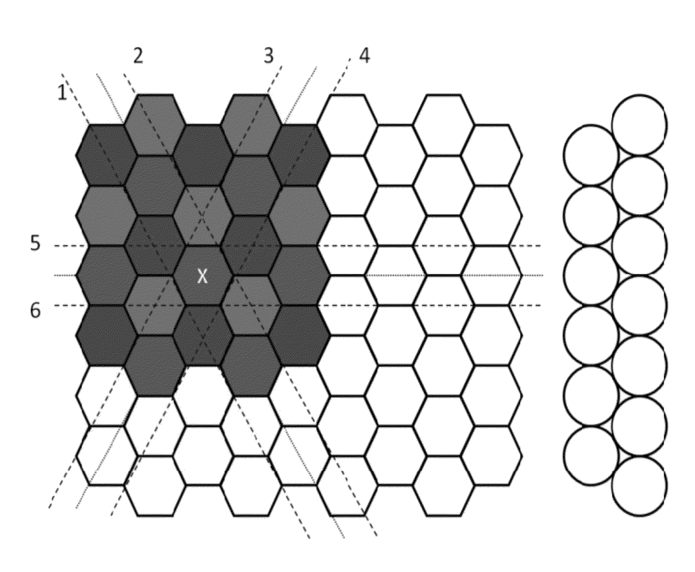
[0041]As shown in FIG. 10b, a reference Tag 2 (REF Tag 2), contains a central hexagon surrounded by two layers of identical hexagons. This tag has a capacity of up to 39 bits when the coding is rotationally invariant. As a comparison, a full longitude-latitude co-ordinate pair requires only 21 bits. The hexagons are regular: if the hexagon side is A, then its height is A√{square root over (3)}. The used colors are black, Red, Yellow, Green, Cyan, Blue, Magenta, and white, in this order.

[0042]IMAGE 1 illustrates a somewhat unusual physical embodiment of the visual reference A Tag. This is a real life photograph showing the projection of dichroic filtered colors by a “Dolce Vita” Oligo halogen lamp, Ref. 5), in the inventor's flat. Note that the Cyan filter is missing. The filters could be switched manually so as to share one of the 5!=120 secret messages, for example.

[0043]FIG. 5 illustrates how covering the plane with circles of a given radius (right) is well approximated by the hon...


PUM


Abstract

A visual Reference tag is formed from an array of cells, wherein each cell is visually distinct from all other cells in a given neighborhood and each of said cells contains a single visual cue, for example a unique color, selected from a finite number of visual cues.

Description

[0001]This application claims benefit of provisional patent application 61 / 373,804, filed Aug. 14, 2010. This patent or application file contains at least one drawing and photograph executed in color. Copies of this patent or patent application publication with color drawing(s) will be provided by the Office upon request and payment of necessary fee.BACKGROUND OF THE INVENTION[0002]This invention relates to producing, capturing and using visual identification tags for moving objects. More particularly, this invention addresses the need to identify one or more moving objects with the help of a standard digital camera, like a web-camera or video-frames of a mobile phone camera.[0003]A bar code contains information represented by a linear series of spaced lines, wherein the width of the lines and spacing there between varies. The code can be scanned to retrieve information represented by the spacing. A problem associated with bar codes is that they are difficult to read at a distance, ...

Claims


Application Information

Patent Timeline
Patent Type & Authority Applications(United States)
IPC IPC(8): G06K9/34
CPCG06K7/1417G06K7/1473G06K19/06037G06K19/06046G06K19/06075G06K19/06103G06K19/0614
Inventor RUJAN, PAL
Owner RUJAN ENTWICKLUNG & FORSCHUNG
Learn More