Indoor unit of air-conditioning apparatus and air-conditioning apparatus
a technology of air-conditioning apparatus and air-conditioning equipment, which is applied in the direction of lighting and heating equipment, ventilation systems, heating types, etc., can solve the problems of inability to distribute airflows of different air volumes individually to different places in the room, and achieve the effect of avoiding the possibility of affecting the airflow distribution
- Summary
- Abstract
- Description
- Claims
- Application Information
AI Technical Summary
Benefits of technology
Problems solved by technology
Method used
Image
Examples
embodiment 1
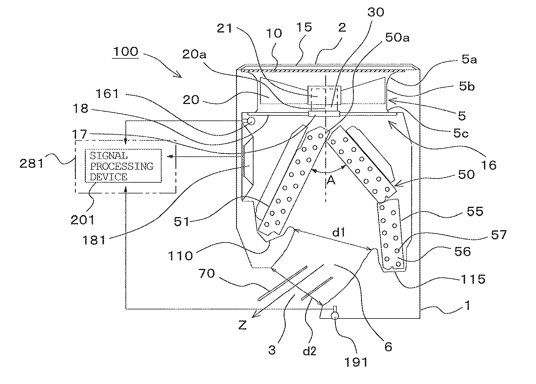
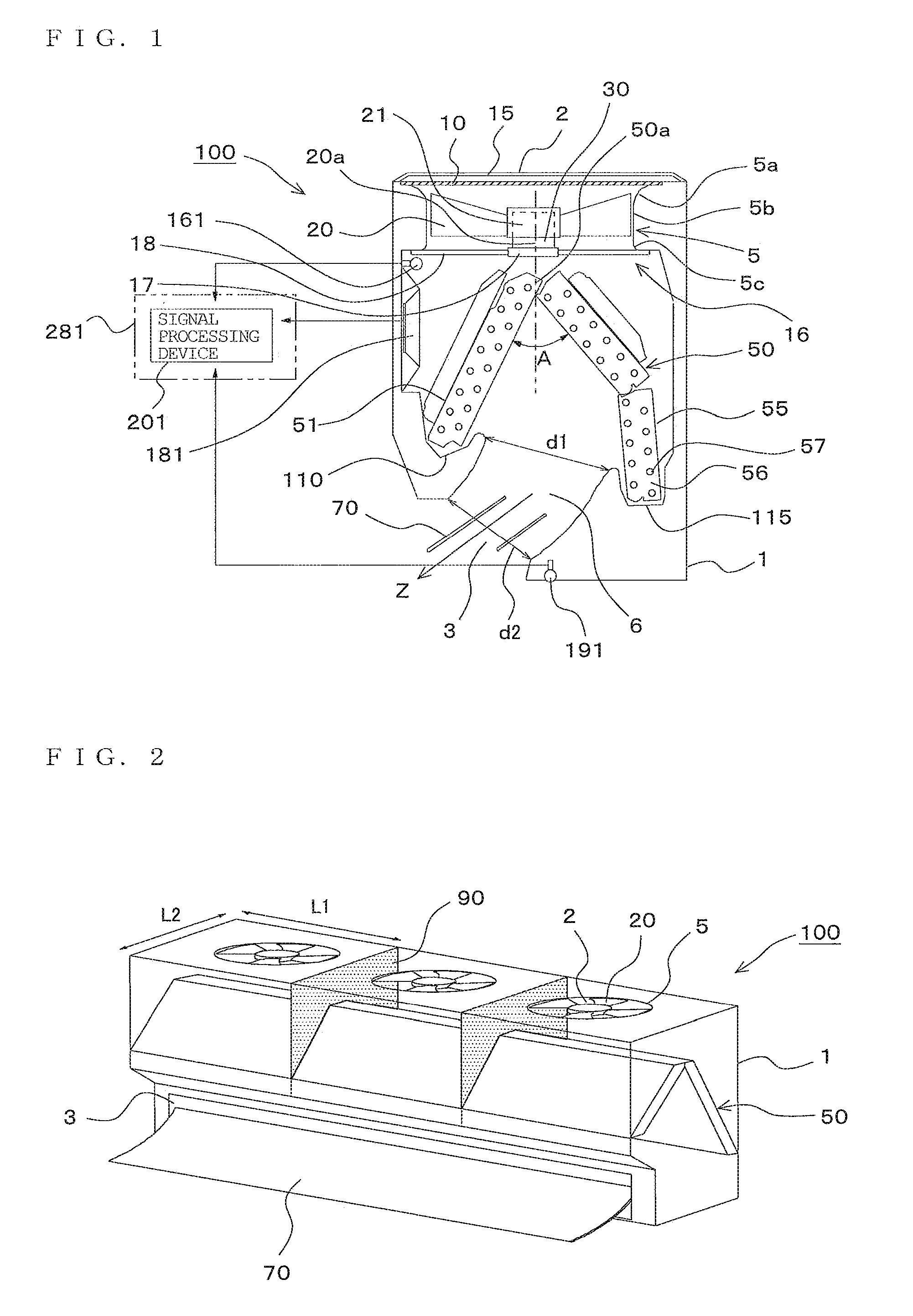
[0034]FIG. 1 is a vertical cross-sectional view illustrating an indoor unit (referred to as “indoor unit 100”) of an air-conditioning apparatus according to Embodiment 1 of the invention. FIG. 2 is a perspective view illustrating the indoor unit shown in FIG. 1. In the description of Embodiment 1 and other embodiments described later, the left side in FIG. 1 is defined as the front side of the indoor unit 100. Referring now to FIG. 1 and FIG. 2, a configuration of the indoor unit 100 will be described.
(General Configuration)
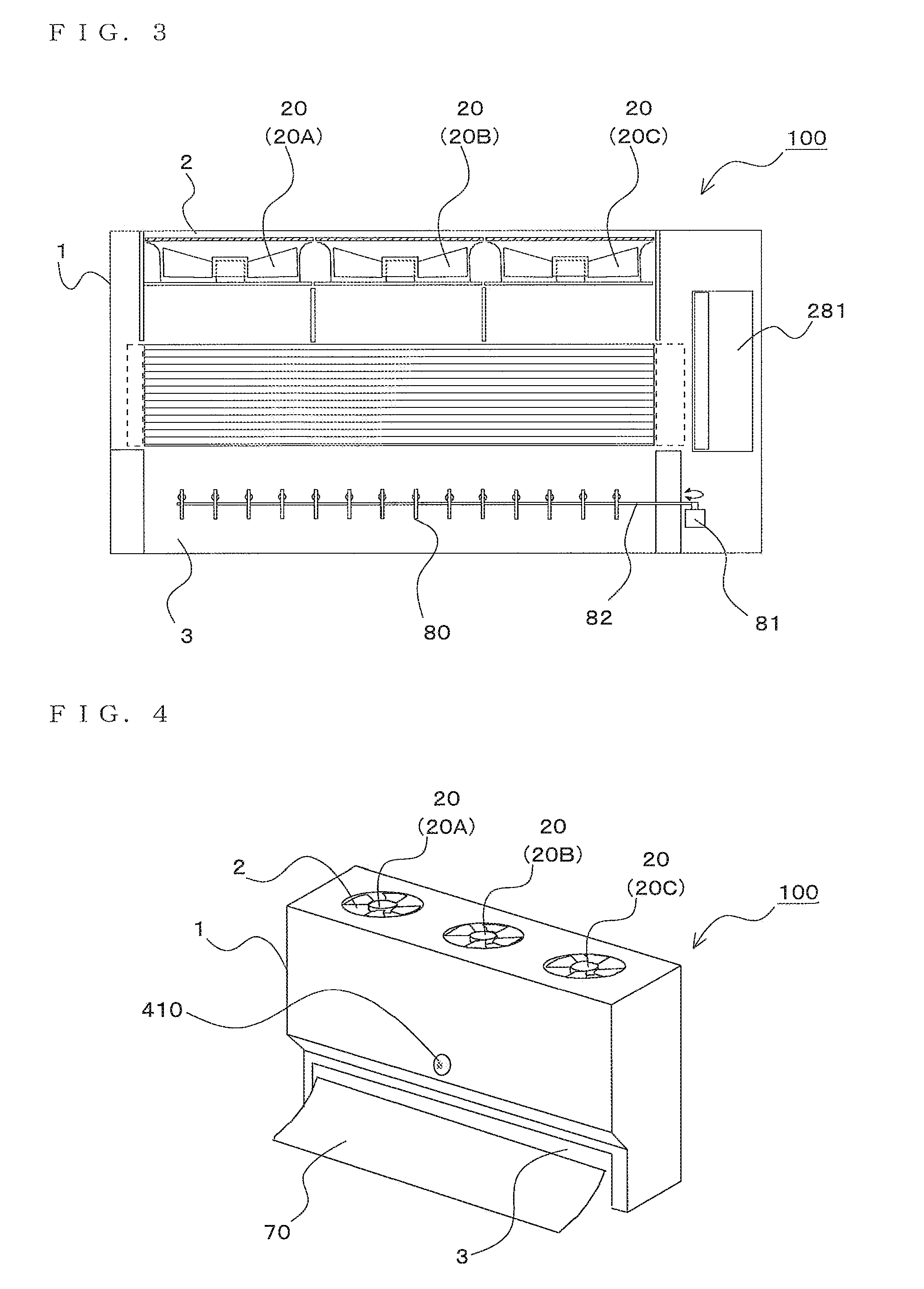
[0035]The indoor unit 100 supplies air-conditioned air to an area to be air-conditioned such as an indoor space by utilizing a refrigerating cycle circulating a refrigerant. The indoor unit 100 mainly includes a casing 1 formed with suction ports 2 for taking in indoor air and a blow-out port 3 for supplying air-conditioned air to the area to be air-conditioned, fans 20 housed in the casing 1 and configured to take in the indoor air from the suction ports 2 and b...
embodiment 2
[0118](Dividing Vane into Plurality of Parts)
[0119]When controlling the vertical wind direction control vane 70, the horizontal wind direction control vane 80, and the air volume of each fans 20 on the basis of the results of detection by the infrared ray sensor 410, dividing the vertical wind direction control vane 70 and the horizontal wind direction control vane 80 into a plurality of parts and controlling the same individually is recommended. Accordingly, comfort can further be improved. In Embodiment 2, items not specifically described are the same as those in Embodiment 1, and the same numbers reference the same functions and configurations in the description.
[0120]FIG. 11 is a front cross-sectional view illustrating the indoor unit according to Embodiment 2 of the invention. FIG. 12 is a perspective view illustrating the same indoor unit. FIG. 11 is a front cross-sectional view taken along the substantially center portions of the fans 20.
[0121]In the indoor unit 100 according...
embodiment 3
[0128](Dividing Vane into Number of Parts as Same as the Number of Fans)
[0129]By increasing the number of divisions of the vertical wind direction control vane 70 and the horizontal wind direction control vane 80, the comfort can further be improved. Also, by employing the number of divisions of the vertical wind direction control vane 70 and the horizontal wind direction control vane 80 as many as the number of the fans 20, the comfort can further be improved. In Embodiment 3, items not specifically described are the same as those in Embodiment 1 and Embodiment 2, and the same numbers reference the same functions and configurations in the description.
[0130]FIG. 13 is a front cross-sectional view illustrating the indoor unit according to Embodiment 3 of the invention. FIG. 14 is a perspective view illustrating the same indoor unit. FIG. 13 is a front cross-sectional view taken along the substantially center portions of the fans 20. The indoor unit 100 shown in FIG. 13 and FIG. 14 sh...
PUM
 Abstract
Description
Claims
Application Information
 - Generate Ideas
- Intellectual Property
- Life Sciences
- Materials
- Tech Scout
- Unparalleled Data Quality
- Higher Quality Content
- 60% Fewer Hallucinations
Browse by: Latest US Patents, China's latest patents, Technical Efficacy Thesaurus, Application Domain, Technology Topic, Popular Technical Reports.
© 2025 PatSnap. All rights reserved.Legal|Privacy policy|Modern Slavery Act Transparency Statement|Sitemap|About US| Contact US: help@patsnap.com


