
Alarm system IP network with pstn output

a technology of alarm system and ip network, applied in the field of alarm system monitoring over the internet, can solve the problems of small alarm company that may find themselves unable to compete with larger companies

Active Publication Date: 2012-02-02
SIERRA WIRELESS AMERICA
View PDF5 Cites 28 Cited by
  • Summary
  • Abstract
  • Description
  • Claims
  • Application Information

AI Technical Summary

Benefits of technology

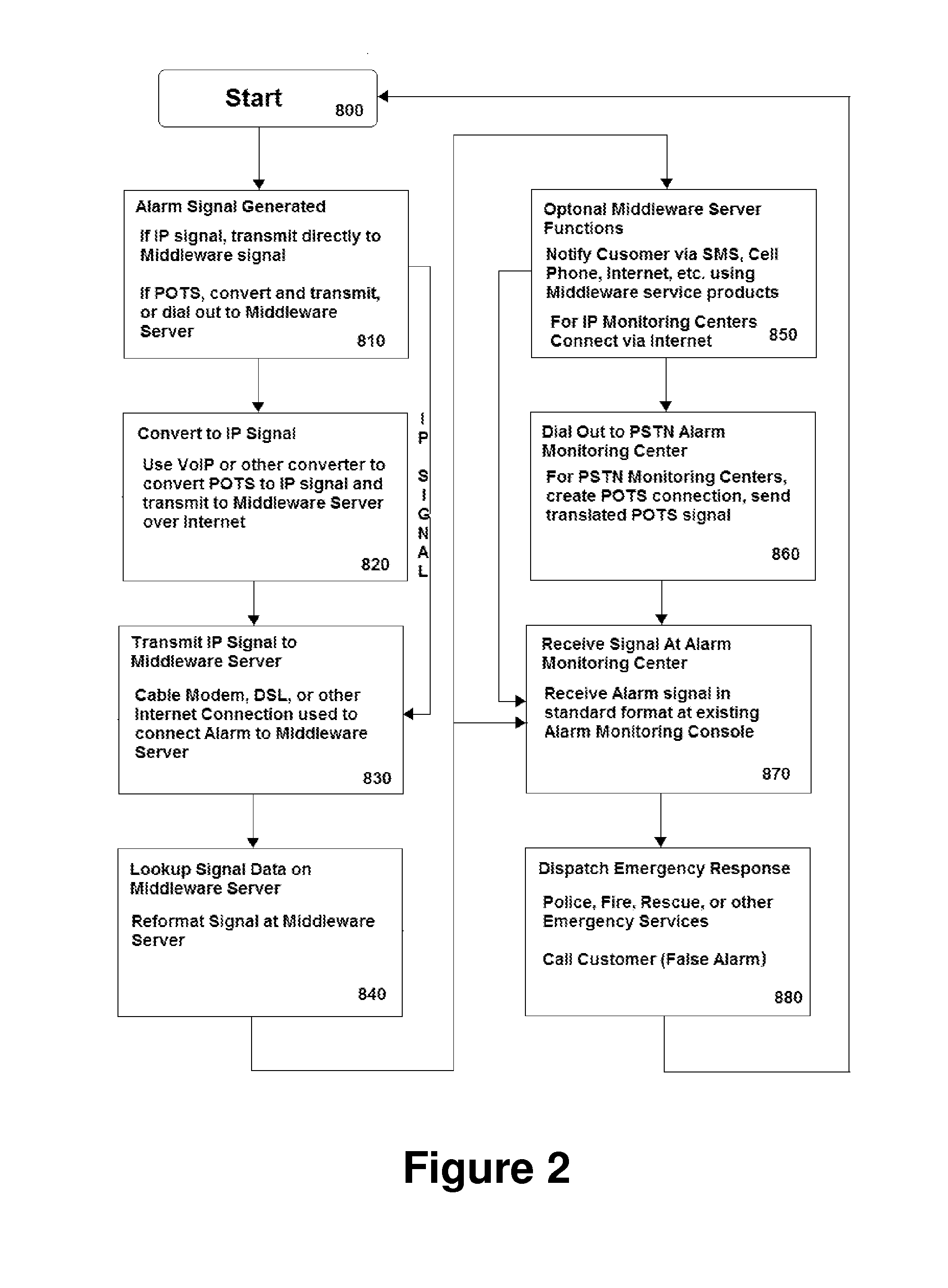
[0007]Alarm customers on VoIP may now use an adapter developed by the present inventors, for conversion to IP (Internet Protocol) as disclosed in Applicant's previous patent applications previously incorporated by reference. In the present invention, IP signals from customers can go to any monitoring center—those with corresponding servers on IP directly and those without corresponding servers, using the central server (middleware provider) of the present invention to dial on POTS (Plain Old Telephone Service) to the monitoring center or by communicating directly with the monitoring center over an IP link. IN this manner, the middleware server can take a number of alarm signals from disparate alarm system types, formats and paths (IP or POTS) and output them in a single format, which may be used by the alarm monitoring company. In one particular embodiment of the present invention, IP signals are translated back into POTS signals, such that an alarm monitoring company using POTS equipment can monitor IP alarm signals.

Problems solved by technology

One problem with Internet monitoring of alarm systems is that there are a number of such IP alarm systems or converters (such as developed by the present inventors) on the market, and each may have its own particular format and central station monitoring hardware or software.
Moreover, since such alarm monitoring systems may be “stand alone”, the alarm monitoring company may have to maintain and monitor such separate systems, meaning that the monitoring personnel have to monitor and respond to multiple screens of data, each in a different format and using a different command and menu structure—and each requiring separate training.
Such smaller alarm companies may find themselves unable to compete with larger companies, particularly as more and more customers switch to VoIP or IP based alarm protocols.

Method used


Image

  • Alarm system IP network with pstn output
  • Alarm system IP network with pstn output
  • Alarm system IP network with pstn output

Examples


Embodiment Construction

[0015]The alarm translation system of the present invention is discussed below in connection with FIGS. 1 and 2.

[0016]One key to understanding the present invention is that in the alarm monitoring business, alarm monitoring companies and the company providing the alarm services may be two different entities. Thus, for example, if a customer contracts with ACME Alarm Systems Company for alarm services, ACME may in turn subcontract out the actual day-to-day monitoring of the customer's alarm system to a third party—perhaps even offshore—where operating costs are lower. The Alarm company may provide a branded identity (ACME) to the customer, as well as service (installation, repair) of the physical alarm system, billing services, and also middleware services, as described elsewhere in applicant's previous applications incorporated by reference.

[0017]However, Prior Art alarm systems use a number of formats to generate and transmit alarms, from early POTS (Plain Old Telephone Service) sy...


PUM


Abstract

Alarm customers on VoIP may use an adapter for conversion to Internet Protocol (IP) signals or may have an alarm system that uses IP signals to transmit alarm signals over the Internet. IP signals from alarm customers may go to any monitoring center for alarm system monitoring. IP signals from alarm systems using IP conversion equipment can go only to monitoring centers with specialized receiving equipment specific to the type of transmitting equipment in use at the customer's premises. There is a pool of customers, whose dealers would convert to IP and stay with the current monitoring center if the center invested in receiving equipment. For the many small centers who will not or cannot invest in receiving equipment, the present invention will take IP signals from any or all brands of IP transmitting equipment, to a central server then retransmit to any center over POTS to the alarm monitoring center. Thus, an alarm monitoring center need not invest in a number of different IP monitoring systems in order to be IP monitoring compliant.

Description

CROSS-REFERENCE TO RELATED APPLICATIONS[0001]The present application is also a Continuation-In-Part (CIP) of co-pending U.S. patent application Ser. No. 13 / 004,917 (ELLIOT-0010) filed on Jan. 12, 2011 and incorporated herein by reference; application Ser. No. 13 / 004,917 is a Continuation-In-Part application of U.S. patent application Ser. No. 12 / 018,724 (ELLIOT-0008), filed on Jan. 23, 2008 and incorporated herein by reference, which in turn is a Continuation-In-Part of U.S. patent application Ser. No. 11 / 517,025 (ELLIOT-0007), filed on Sep. 7, 2006, and incorporated herein by reference; which in turn is a Continuation-In-Part of U.S. patent application Ser. No. 11 / 226,857 (ELLIOT-0005) filed on Sep. 14, 2005 and incorporated herein by reference; application Ser. No. 11 / 226,857 in turn claims priority from Provisional U.S. Patent Application Ser. No. 60 / 651,662 (ELLIOT-0004) filed on Feb. 11, 2005 and incorporated herein by reference; application Ser. No. 11 / 226,857 is also a Contin...

Claims


Application Information

Patent Timeline
Patent Type & Authority Applications(United States)
IPC IPC(8): H04L12/66G08B23/00
CPCH04L12/1471H04L12/66H04L12/413H04L12/40013G08B29/02
Inventor ELLIOT, HARVEY ALEXANDERFIELD-ELLIOT, BRYANELLIOT, DANIEL
Owner SIERRA WIRELESS AMERICA
Learn More