Method for controlling light-emitting diodes

Inactive Publication Date: 2012-02-02
VALEO VISION SA
View PDF3 Cites 7 Cited by
  • Summary
  • Abstract
  • Description
  • Claims
  • Application Information

AI Technical Summary

Benefits of technology

[0018]In particular, one embodiment of the present invention is the implementation of a method for gradually controlling the illuminating light intensity of LEDs, which enables power to be supplied to the LEDs conditionally upon the steady state of the power supply pulses determined for the latter, thereby substantially reducing, if not removing, any imprecision in the gradual control of the illuminating light intensity finally obtained at low lighting levels.

Problems solved by technology

In particular, for conventional DC-to-DC converter circuit / switchable control circuit pairs, since the switchable control circuit comprises a proportional-integral loop for controlling the voltage level of the pulses, the limited dynamic, i.e., response time, of the assembly thus arranged means that the power supplied to the LEDs takes too long to settle.
Furthermore, when a gradual control of the illuminating light intensity of the LEDs is applied so as to obtain low lighting level, the duty cycle of the supply pulses then being set to a value lower than a value of about 20%, the excessively slow rise time of the pulses reduces the average value of the current supplied to the LEDs, which average value is no longer equal to the product of the amplitude value of the pulses in the steady state and the duty cycle value used for application of the gradual control.
This results in a non-linearity of the gradual control, which causes this control to be less precise.
This is not the case for conventional switchable control circuits normally available on the market.

Method used


Image

  • Method for controlling light-emitting diodes
  • Method for controlling light-emitting diodes
  • Method for controlling light-emitting diodes

Examples


Embodiment Construction

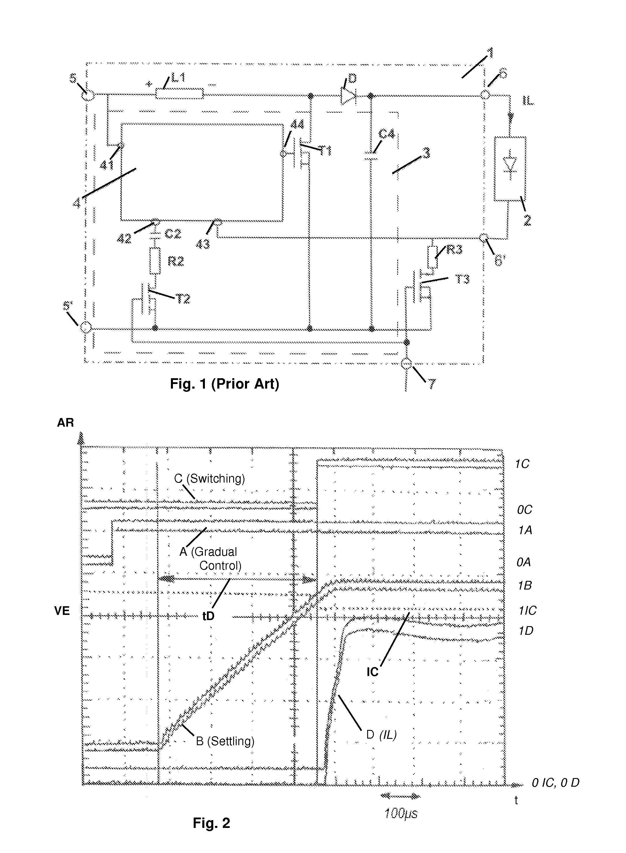
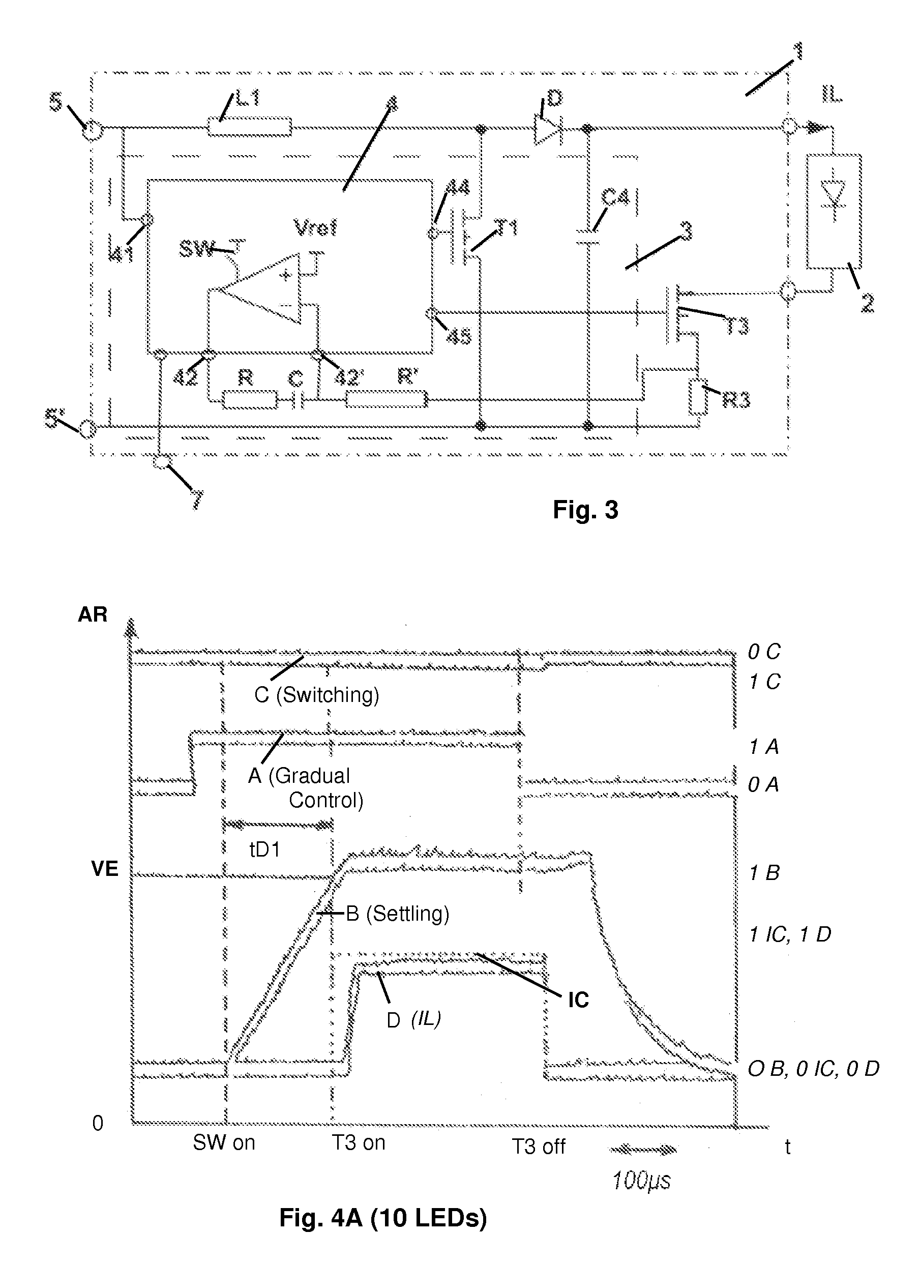
[0036]A more detailed description of the method that is a subject of the invention will now be given in relation to FIG. 2. In FIG. 2 and FIGS. 4A and 4B, which show timing diagrams of signals recorded using a multi-channel oscilloscope, the relative amplitude RA is measured along the Y-axis, showing in fact the high and low levels of the various signals, and time is measured along the X-axis, 1 cm representing 100 μs.

[0037]The aforementioned method, in a non-limiting way, preferably relates to the gradual control of the illuminating light intensity of light-emitting diodes by modulating the width of current pulses, the duty cycle of which pulses is defined, depending on the use, in particular when this duty cycle is lower than 20%, for example, using a DC-to-DC voltage converter and a control circuit for switching the current supplied to the light-emitting diodes.

[0038]With reference to the aforementioned FIG. 2, the method consists, at least in succession, in initiating, A, the DC...


PUM


Abstract

A method and a device for gradually controlling the illuminating light intensity of light-emitting diodes by modulating the width of current pulses of defined duty cycle, using a DC-to-DC voltage converter and a control circuit for switching the supply current of the light-emitting diodes. Prior to switching the power supply of the diodes the DC-to-DC converter is initiated (A), so as to generate voltage pulses of defined duty cycle; the steady state of each pulse is determined (B), so as to generate a voltage pulse (CP) calibrated to a voltage level substantially corresponding to the steady-state level; and then the light-emitting diodes are powered (D) by applying each calibrated pulse to the light-emitting diodes by means of the switchable control circuit.

Description

CROSS-REFERENCE TO RELATED APPLICATIONS[0001]This application claims priority to French Application No. 1055735 filed Jul. 13, 2010, which application is incorporated herein by reference and made a part hereof.BACKGROUND OF THE INVENTION[0002]1. Field of the Invention[0003]This invention relates to light-emitting diodes and more particularly, a system and method for controlling light-emitting diodes.[0004]2. Description of the Related Art[0005]At the present time light-emitting diodes, denoted LEDs hereafter, are increasingly being used to provide lighting and / or signalling functions for automotive vehicles.[0006]Generally, several LEDs are associated in an optical unit and powered synchronously so as to ensure the aforementioned functions.[0007]When, in particular, a gradual control of the illuminating light intensity, or dimming, of the LEDs must be achieved, the aforementioned groups of LEDs lend themselves satisfactorily to such a control mode, by means of a modulation of the du...

Claims


Application Information

Patent Timeline
IPC IPC(8): H05B37/02H05B44/00
CPCH05B33/0818H05B33/0851H05B33/0824H05B45/10H05B45/44H05B45/38H05B45/3725
Inventor KRICK, SEBASTIANFLANDRE, LOIC
Owner VALEO VISION SA
Why Eureka
Try Eureka