
Vehicle ac generator

a generator and alternating current technology, applied in the direction of dynamo-electric components, dynamo-electric brakes/clutches, association for rectification, etc., can solve the problems of increasing affecting the efficiency of the generator, so as to reduce the total shaft length of the generator and easily set the attachment direction of the battery terminal.

Inactive Publication Date: 2012-02-02
MITSUBISHI ELECTRIC CORP
View PDF3 Cites 6 Cited by
  • Summary
  • Abstract
  • Description
  • Claims
  • Application Information

AI Technical Summary

Benefits of technology

The present invention is about a vehicle AC generator that can easily attach a battery terminal and reduce the overall length of the generator. It includes a case composed of a front bracket and a rear bracket, and a rotor and stator arranged inside the case. The generator also has a battery terminal on the rear bracket, an engaging body on the battery terminal, and multiple fitting portions to which the engaging body is fitted. This design allows for easy attachment direction of the battery terminal and reduces the overall length of the generator.

Problems solved by technology

Each of these components is a formed component by a die and, in the case of new set, unnecessary costs are incurred.
Furthermore, variations of components increase and therefore various disadvantages such as degradation in productivity are incurred.
However, the battery terminal is located on the surface of the cover or the bracket; therefore, there is a demerit in that the battery terminal largely protrudes from the backward side of the generator and the total shaft length of the generator increases.

Method used


Image

  • Vehicle ac generator
  • Vehicle ac generator
  • Vehicle ac generator

Examples


embodiment 1

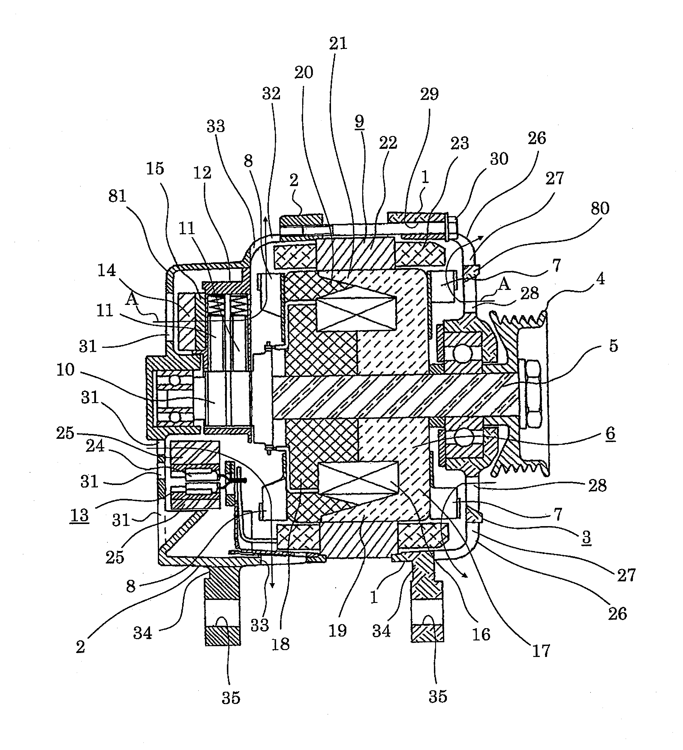
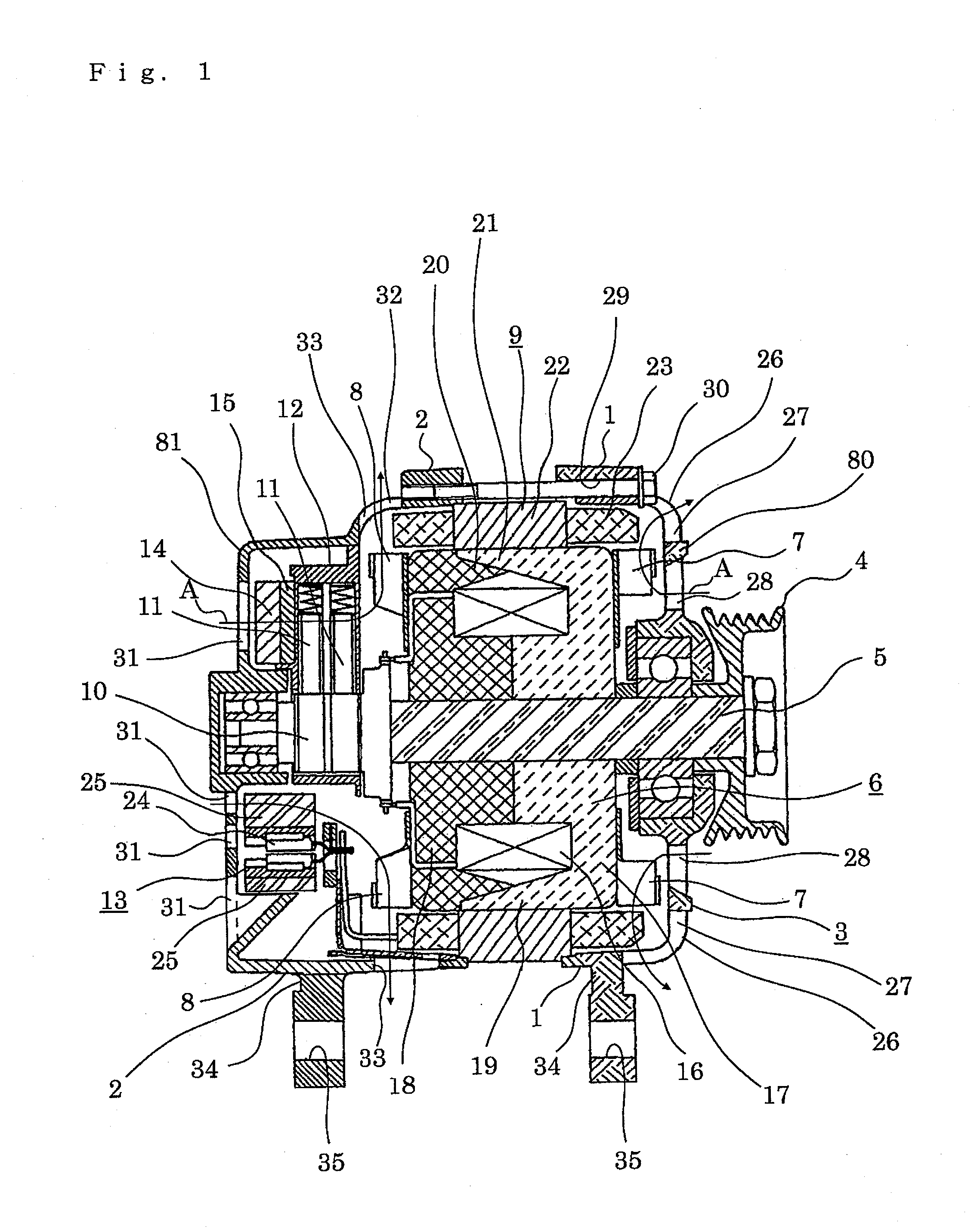
[0018]Hereinafter, Embodiment 1 of the present invention will be described with reference to FIG. 1 to FIG. 4; however, in each of the drawings, identical or equivalent members and portions will be described with the same reference numerals. FIG. 1 is a sectional view showing a rear bracket type in a vehicle AC generator according to Embodiment 1 of the present invention. FIG. 2 is a front view showing a cover of a cover type in the vehicle AC generator according to Embodiment 1 of the present invention. FIG. 3 is a sectional view showing a battery terminal portion in the vehicle AC generator according to Embodiment 1 of the present invention. FIG. 4 is a sectional view showing the battery terminal portion in the vehicle AC generator according to Embodiment 1 of the present invention.

[0019]The vehicle AC generator in Embodiment 1 includes a case 3 composed of a front bracket 1 and a rear bracket 2, both of which are made of aluminum; a shaft 5 provided in the case 3 and provided wit...


PUM


Abstract

In order to provide a vehicle AC generator capable of easily setting an attachment direction of a battery terminal and reducing the total shaft length of the generator, in the vehicle AC generator including a case composed of a front bracket and a rear bracket, and a rotor and a stator which are arranged in the case, the vehicle AC generator includes a battery terminal arranged on an outer circumferential portion of the rear bracket, an engaging body provided on the battery terminal, and a plurality of fitting portions to which the engaging body is fitted.

Description

BACKGROUND OF THE INVENTION[0001]1. Field of the Invention[0002]The present invention relates to a vehicle AC (alternating current) generator mounted on a vehicle and, more particularly, relates to an attachment structure of a battery terminal for power output.[0003]2. Description of the Related Art[0004]Hitherto, a battery terminal for power output has been attached to a vehicle AC generator at the back of the generator. There are largely two types of generator structures. First, one type is such that components such as a rectifier and a voltage regulator (hereinafter, referred to as a “regulator”) are arranged inside a bracket serving as a housing. The other type is such that those components are arranged outside the bracket and are protected by a resin-made cover.[0005]In the former case, the battery terminal is attached to a rear bracket; in the latter case, the battery terminal is attached to the cover. Then, an attachment direction of the battery terminal is determined by the ...

Claims


Application Information

Patent Timeline
Patent Type & Authority Applications(United States)
IPC IPC(8): H02K5/00
CPCH02K11/046H02K5/225H02K11/05
Inventor SHINOSAKA, YOSHIHIRO
Owner MITSUBISHI ELECTRIC CORP
Learn More