
System and method for monitoring wind turbine gearbox health and performance

a technology for wind turbine gearboxes and monitoring systems, applied in the direction of electric generator control, machines/engines, instruments, etc., can solve the problems of significant variations in bearing and gear vibration feature frequencies, the most expensive component of wind turbine gearboxes to purchase, maintain and repair, and the main shaft speed is not precisely controlled

Inactive Publication Date: 2012-02-02
GENERAL ELECTRIC CO
View PDF16 Cites 211 Cited by
  • Summary
  • Abstract
  • Description
  • Claims
  • Application Information

AI Technical Summary

Problems solved by technology

The wind turbine gearbox is generally the most expensive component to purchase, maintain, and repair.
Moreover, in operation, the main shaft speed is not precisely controlled.
A small variation in the main shaft speed may cause significant variations in the bearing and gear vibration feature frequencies, especially those associated with the high-speed shaft.
As a result, the conventional vibration monitoring system may be less effective in providing reliable information under all operating conditions.

Method used


Image

  • System and method for monitoring wind turbine gearbox health and performance
  • System and method for monitoring wind turbine gearbox health and performance
  • System and method for monitoring wind turbine gearbox health and performance

Examples


Embodiment Construction

[0015]Embodiments of the invention will be better understood when read in conjunction with the appended drawings. To the extent that the figures illustrate diagrams of the functional blocks of various embodiments, the functional blocks are not necessarily indicative of the division between hardware circuitry. Thus, for example, one or more of the functional blocks (e.g., processors, controllers or memories) may be implemented in a single piece of hardware (e.g., a general purpose signal processor or random access memory, hard disk, or the like) or multiple pieces of hardware. Similarly, the programs may be stand alone programs, may be incorporated as subroutines in an operating system, may be functions in an installed software package, and the like. It should be understood that the various embodiments are not limited to the arrangements and instrumentality shown in the drawings.

[0016]As used herein, an element or step recited in the singular and proceeded with the word “a” or “an” s...


PUM


Abstract

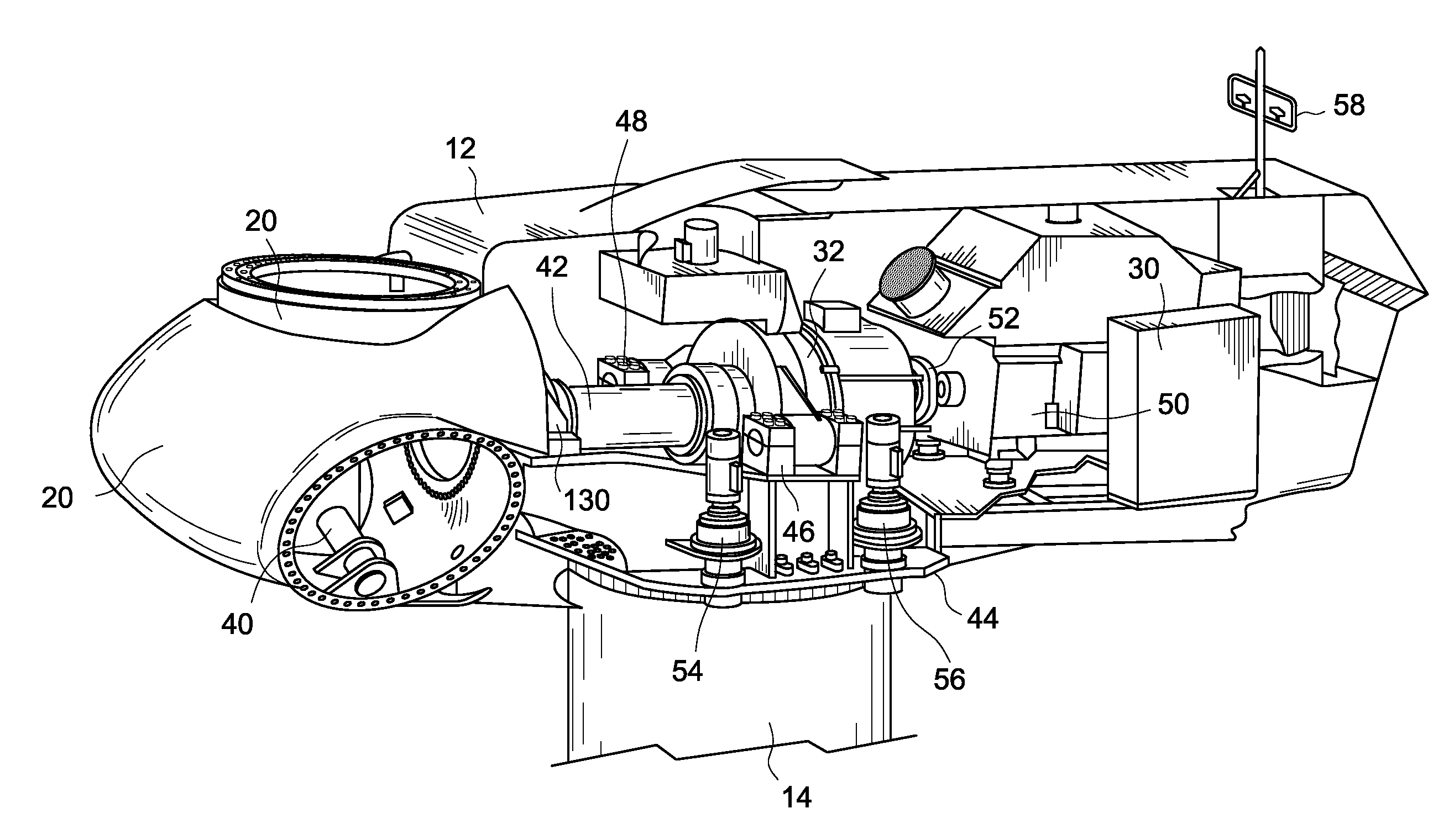
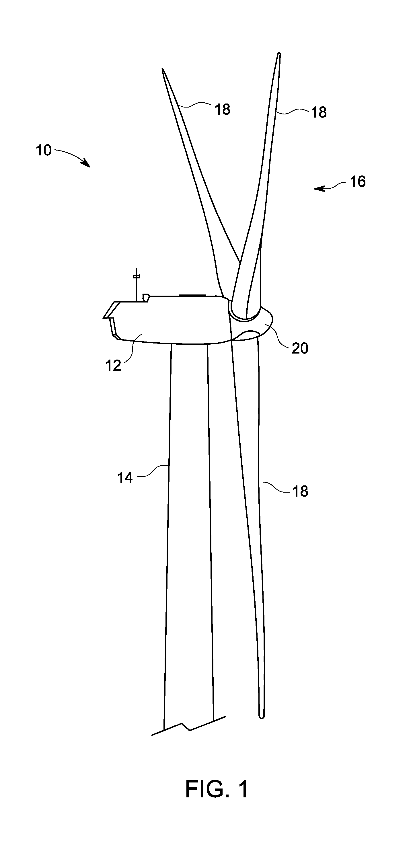
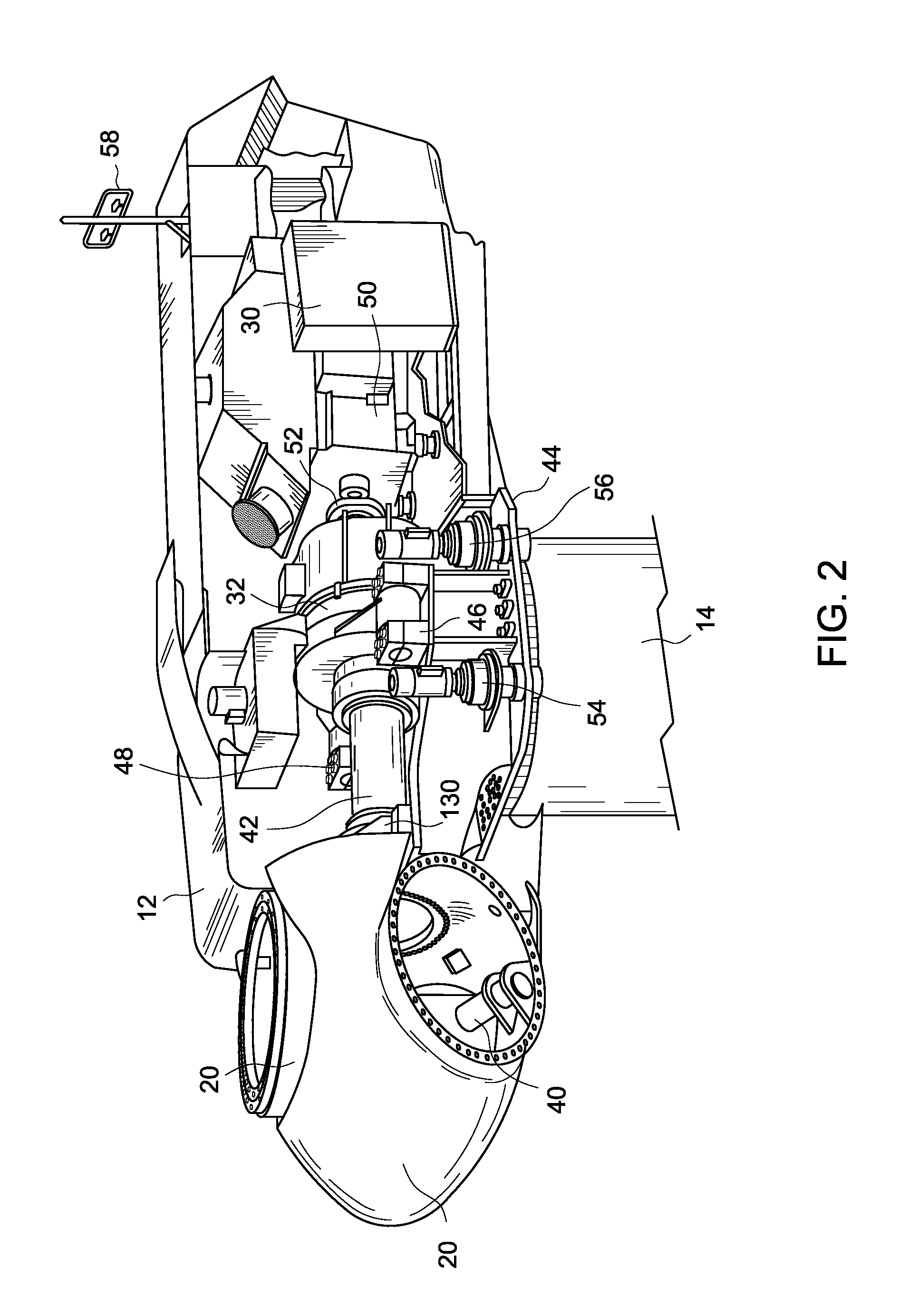
A system and method are provided to monitor the health and performance of a wind turbine gearbox. A plurality of sensors coupled to the wind turbine gearbox provide input to a controller. The controller generates output information that includes performance and health information of the wind turbine gearbox based on the input received from each of the sensors.

Description

BACKGROUND OF THE INVENTION[0001]Wind power is one of the fastest growing energy sources around the world. The long-term economic competitiveness of wind power as compared to other energy production technologies is closely related to the reliability and maintenance costs associated with the wind turbine. The wind turbine gearbox is generally the most expensive component to purchase, maintain, and repair.[0002]The conventional vibration monitoring system is based on features uniquely associated with the gearbox bearing design, the gearbox gear design, and the gearbox shaft rotational speeds. For example, a speed of a main rotor is amplified to orders of magnitude by a multi-stage gearbox. Thus, the gear and bearing vibration signatures are high magnitude orders of the main shaft rotational frequency. Moreover, in operation, the main shaft speed is not precisely controlled. Therefore, the rotational speed of the main shaft varies based on the wind conditions and the generator loading....

Claims


Application Information

Patent Timeline
Patent Type & Authority Applications(United States)
IPC IPC(8): H02P9/04G06F19/00
CPCF03D11/0091F03D11/02Y02E10/722F05B2260/80H02P9/04F05B2260/4031F03D15/00F03D17/00Y02E10/72F03D9/25F03D15/10F03D80/70
Inventor LUO, HUAGENGHALLMAN, DARREN LEEHEDEEN, ROBERT ARVINSIRAK, MICHAELRICHTER, DENNIS
Owner GENERAL ELECTRIC CO
Learn More