
Anterior transpedicular screw-and-plate system

a transpedicular screw and plate technology, applied in the field of bone plate, can solve the problems of large load on the anterior cervical screw and plate system, limited use of pedicle screw fixations in the vertebrae area, multi-level cervical spinal procedures, etc., and achieve the effect of expanding the bone plate translation system

Inactive Publication Date: 2012-01-26
DEPUY SYNTHES PROD INC
View PDF17 Cites 36 Cited by
  • Summary
  • Abstract
  • Description
  • Claims
  • Application Information

AI Technical Summary

Benefits of technology

The present invention is about a cervical anterior transpedicular bone fixation device that allows for vertical and horizontal translation between two plates. The device includes a first and second rotatable eccentric member that enable the plates to move relative to each other. The device also includes a concentric compression ring and a threaded locking screw that interacts with the ring to secure the plates in place. The technical effect of this invention is to provide a versatile and effective bone fixation system for cervical spine procedures.

Problems solved by technology

Multilevel cervical spinal procedures result in relatively large loads on anterior cervical screw and plate systems, particularly in cases of severe three-column subaxial cervical spinal injuries and multilevel plated reconstructions in osteoporotic bone.
Additionally, the use of pedicle screw fixations in the vertebrae area are typically limited by the position of the screw because improperly placing the screw results in potential arterial or spinal cord damage.

Method used


Image

  • Anterior transpedicular screw-and-plate system
  • Anterior transpedicular screw-and-plate system
  • Anterior transpedicular screw-and-plate system

Examples


Embodiment Construction

[0029]Certain terminology is used in the following description for convenience only and is not limiting. The words “right”, “left”, “top” and “bottom” designate directions in the drawings to which reference is made. The words “inwardly” and “outwardly” refer to directions toward and away from, respectively, the geometric center of the facet interference screw and designated parts thereof. The words, “anterior”, “posterior”, “superior”, “inferior”, “lateral”, “sagittal”, “axial”, “coronal” and related words and / or phrases designate preferred positions and orientations in the human body to which reference is made and are not meant to be limiting. The terminology includes the above-listed words, derivatives thereof and words of similar import.

[0030]Certain embodiments of the present invention will now be discussed with reference to the aforementioned figures, wherein like reference numerals refer to like components. Preferred embodiments of the present invention are directed to a cervi...


PUM


Abstract

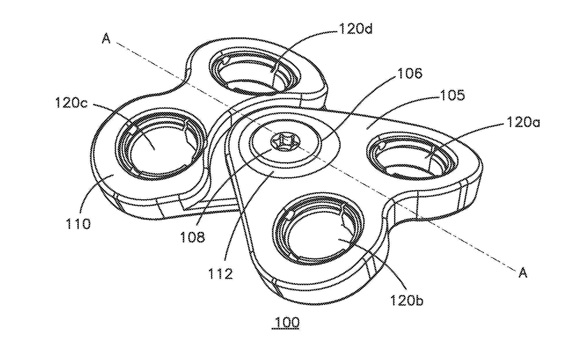
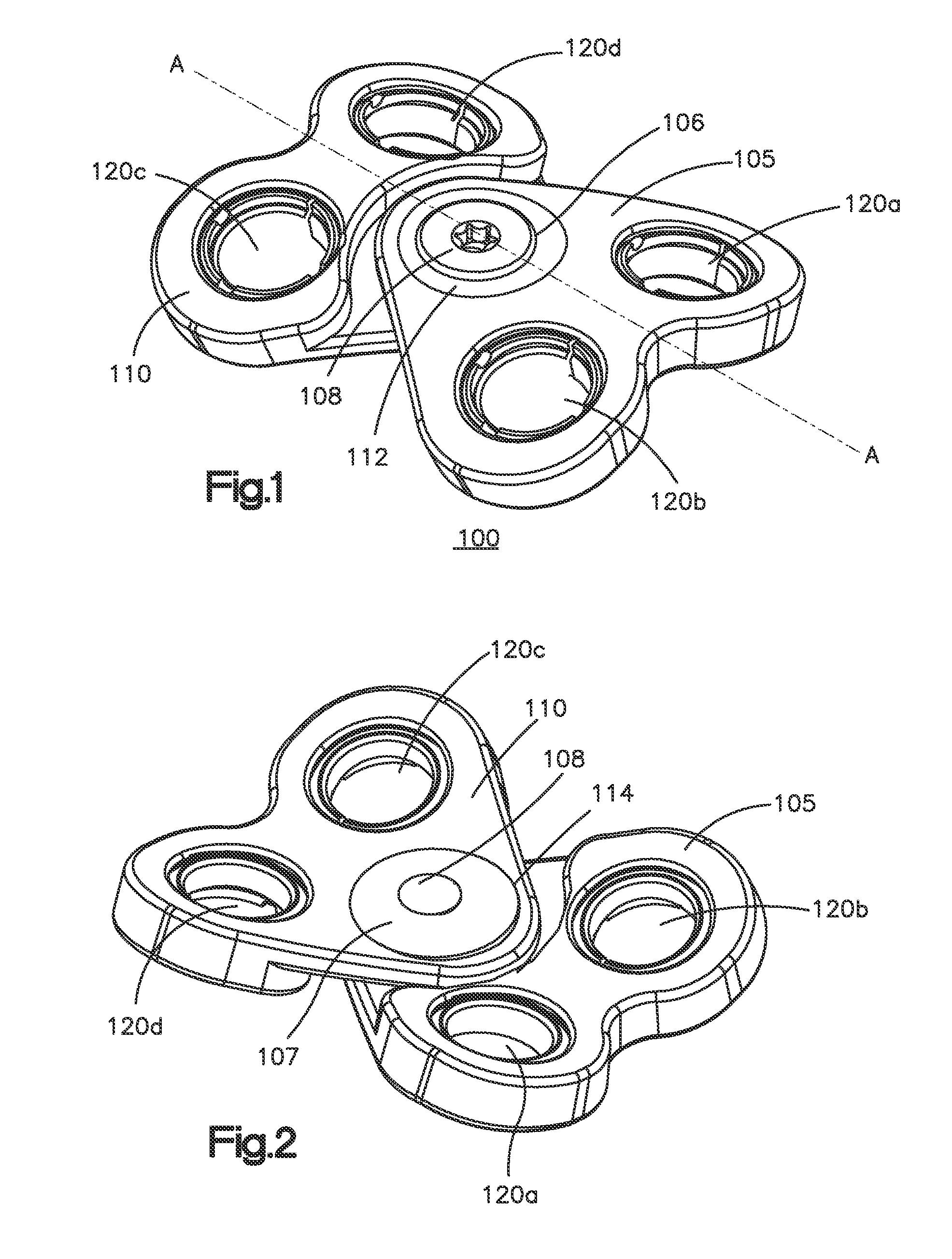
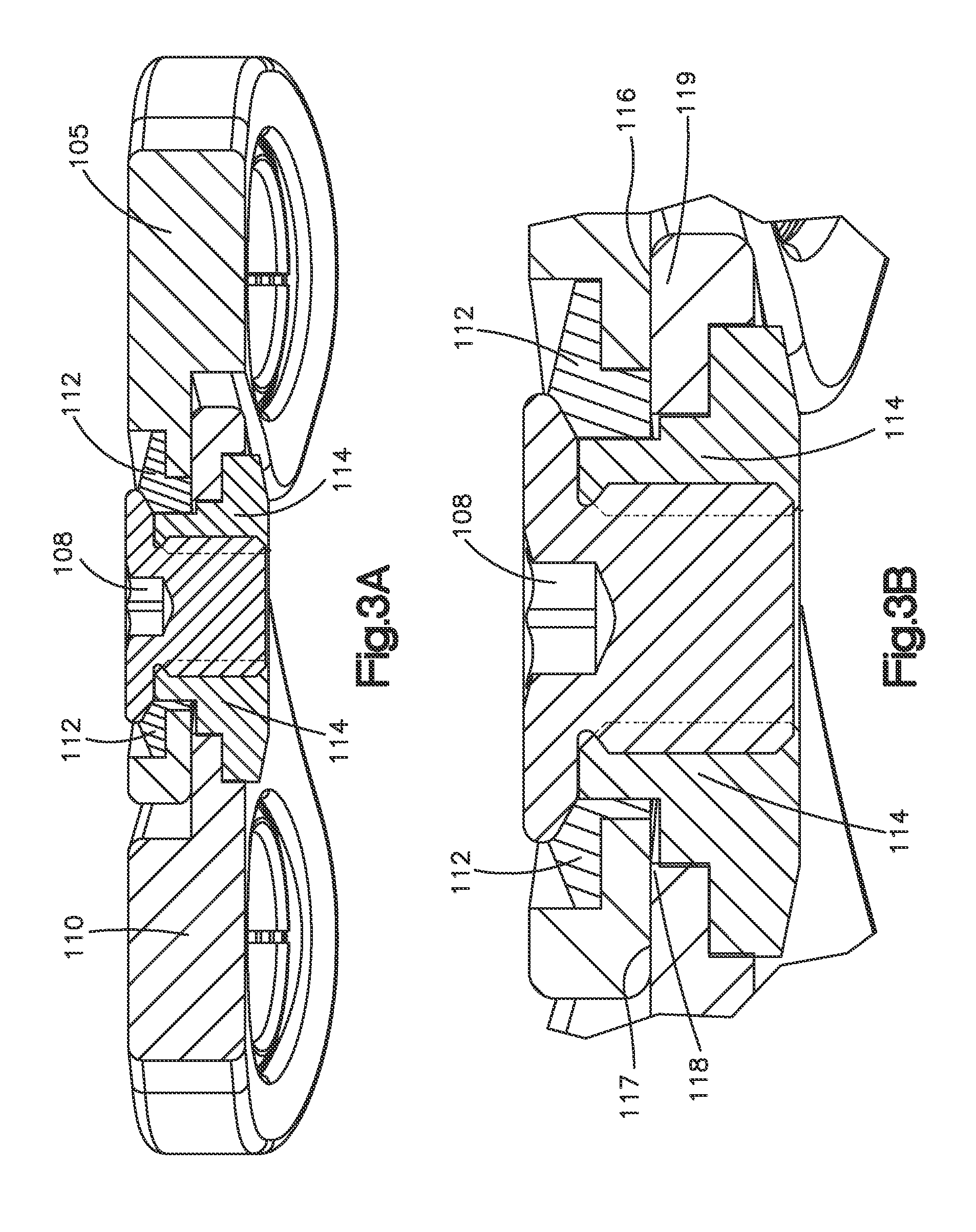
An anterior transpedicular bone fixation device (100) includes a first plate (105) having at least one fastener hole (120a) configured to receive at least a portion of a first bone fastener and a first rotatable eccentric member (112). The first eccentric member has a first aperture (106) for receiving at least a portion of a central fastener (108). A second plate (110) has at least one fastener hole (120c) configured to receive at least a portion of a second bone fastener and a second rotatable eccentric member (114) with a second aperture (107) for receiving at least a portion of the central fastener, wherein the first and second rotatable eccentric members enable the first plate and second plate to translation with respect to one another. The orientation of the first plate with respect to the second plate can be fixed by advancing the central fastener through the apertures.

Description

CROSS-REFERENCE TO RELATED APPLICATIONS[0001]This application claims the benefit of U.S. Provisional Application No. 61 / 098,036, filed on Sep. 18, 2008, entitled “ANTERIOR TRANSPEDICULAR SCREW-AND-PLATE SYSTEM,” the contents of which is incorporated in its entirety by reference herein.BACKGROUND OF THE INVENTION[0002]Multilevel cervical spinal procedures result in relatively large loads on anterior cervical screw and plate systems, particularly in cases of severe three-column subaxial cervical spinal injuries and multilevel plated reconstructions in osteoporotic bone. Supplemental posterior instrumentation is therefore recommended to increase primary construct rigidity and limit potential compromise of the screw and plate systems. The increasing number of successfully performed posterior cervical pedicle screw fixations have enabled more stable fixations, however, most cervical pathologies are located anteriorly and are preferably addressed by an anterior approach.[0003]Additionally...

Claims


Application Information

Patent Timeline
Patent Type & Authority Applications(United States)
IPC IPC(8): A61B17/80
CPCA61B17/7059A61B17/8004A61B17/8061A61B17/8038A61B17/8047A61B17/8023A61B17/70A61B17/80A61B17/86A61F2/44
Inventor OVERES, THOMASZURSCHMIED, SILASFRIGG, ROBERTLECHMANN, BEAT
Owner DEPUY SYNTHES PROD INC
Learn More