
Seal assembly

a technology of sealing lips and seal plates, which is applied in the direction of cantilevered roll stands, manufacturing tools, mechanical equipment, etc., can solve the problems of inability to self-compensate for misalignment, rapid wear and thermal degradation of seal lips,

Active Publication Date: 2012-01-26
PRIMETALS TECH USA
View PDF16 Cites 12 Cited by
  • Summary
  • Abstract
  • Description
  • Claims
  • Application Information

AI Technical Summary

Benefits of technology

[0006]According to another aspect of the present invention, the seal carrier is self aligning to compensate for misalignments between rotating and stationary components resulting from bearing clearances and load induced shaft deflections, thereby maintaining optimum positioning and contact of the ring seals with the flinger flanges.

Problems solved by technology

Such arrangements suffer from several drawbacks, including leakage resulting from rapid wear and thermal degradation of the seal lips, and an inability to self compensate for misalignments between rotating and stationary components resulting from bearing clearances and load induced shaft deflections.

Method used


Image

  • Seal assembly
  • Seal assembly
  • Seal assembly

Examples


Embodiment Construction

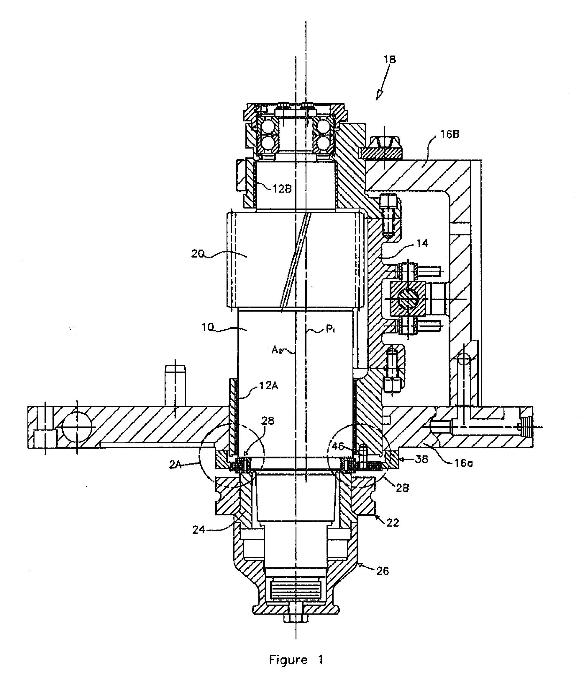
[0011]With reference initially to FIG. 1, a portion of a cantilevered rolling mill is shown in which a roll shaft 10 is journalled for rotation in sleeve bearings 12a, 12b carried in an eccentric cartridge 14, which in turn is journalled for rotation in the front and back plates 16a, 16b of a housing assembly 18. Shaft 10 includes a gear 20 which meshes with another gear of a companion shaft (not shown). An end of the shaft protrudes exteriorly from the front housing plate 16a. A work roll 22 is carried on the exteriorly protruding shaft end, and is fixed in place by an internal tapered sleeve 24 and a cap 26. A seal assembly in accordance with the present invention is generally indicated at 28.

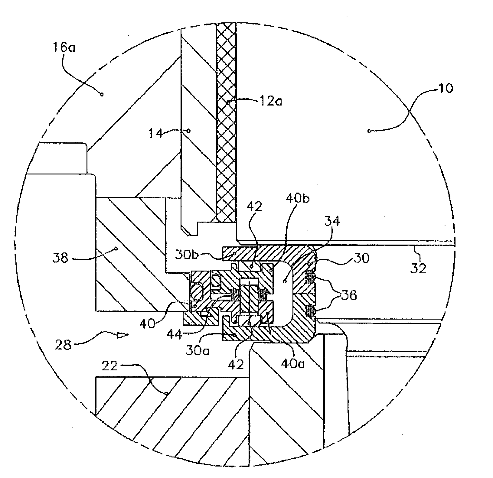
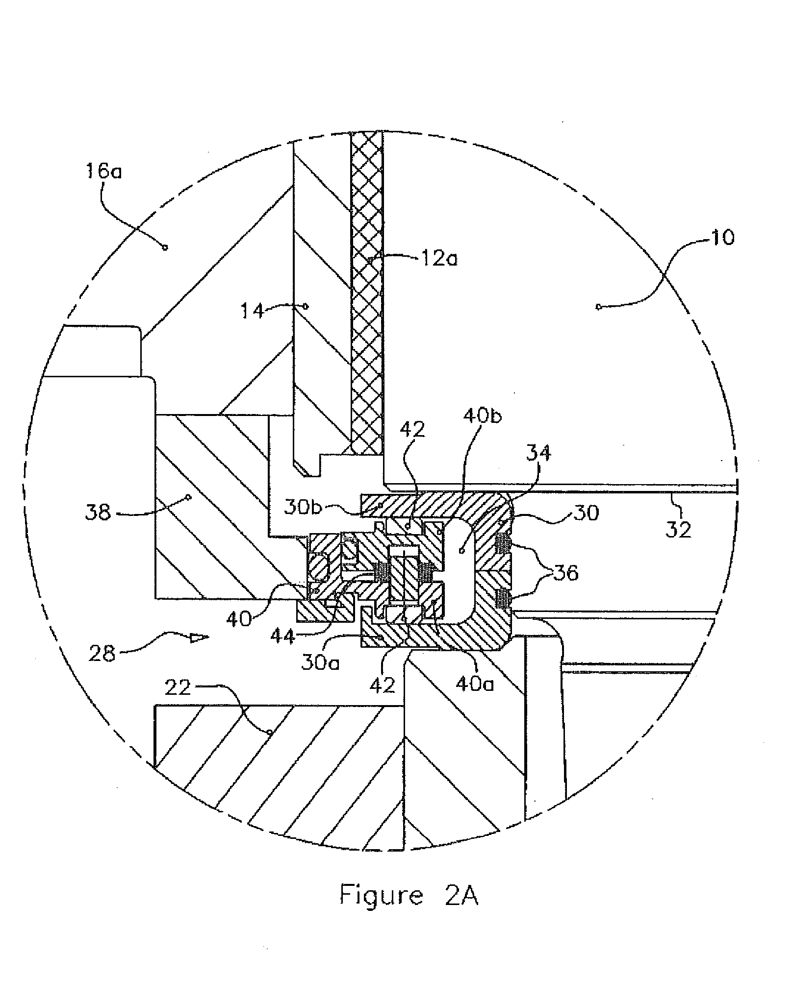
[0012]With reference additionally to FIGS. 2A, 2B and 3, it will be seen that the seal assembly includes a circular flinger 30 mounted on the shaft 10 for rotation therewith. The flinger is captured between a shoulder 32 on the shaft and the work roll 22, and includes radially outwardly proje...


PUM


Abstract

A seal assembly is disclosed for use between a housing and a rotatable shaft protruding exteriorly from the housing, with the shat being journalled for rotation in an eccentric cartridge which in turn is rotatably adjustable. The seal assembly comprises a circular flinger mounted on the shaft for rotation therewith. The flinger has radially outwardly projecting flanges defining an axial space therebetween. A seal carrier surrounds the flinger and has axially spaced first and second inner rims projecting radially inwardly into the space between the flanges of the flinger. Ring seals are carried by the seal carriers. The inner rims are resiliently urged to maintain the ring seals in contact with the flinger flanges.

Description

BACKGROUND OF THE INVENTION[0001]1. Field of the Invention[0002]This invention relates generally to so called “cantilevered” rolling mills, where the work rolls are mounted in an overhung fashion on the ends of roll shafts which protrude from housings containing the shaft bearings, gears, roll parting adjustment mechanisms, etc. The invention is concerned in particular with an improved seal assembly for preventing leakage of lubricants from such housings and for preventing ingress of external contaminants, e.g., cooling water and entrained dirt, mill scale, etc.[0003]2. Description of the Prior Art[0004]As disclosed for example in U.S. Pat. No. 4,910,987 (Woodrow), known seal assemblies typically employ fixed dual lip seals in contact with the adjacent surfaces of flingers mounted on the rotating roll shafts. Such arrangements suffer from several drawbacks, including leakage resulting from rapid wear and thermal degradation of the seal lips, and an inability to self compensate for m...

Claims


Application Information

Patent Timeline
IPC IPC(8): F16J15/16
CPCB21B31/078F16J15/3452B21B13/005F16J15/32B21B31/07
Inventor PRATT, JONATHAN S.SCIALABBA, JOSEPH N.TITUS, DAVID G.
Owner PRIMETALS TECH USA
Learn More