
Prosthetic knee void filers with splined fixation

a joint replacement and void technology, applied in the field of joint replacement systems, can solve the problems of often necessary revision procedures, loss of native bone near the joint being replaced, defects in bone adjacent to the joint, etc., and achieve the effects of fine rotational adjustment, small difference in angular spacing, and improved anatomical fi

Active Publication Date: 2012-01-19
HOWMEDICA OSTEONICS CORP
View PDF40 Cites 40 Cited by
  • Summary
  • Abstract
  • Description
  • Claims
  • Application Information

AI Technical Summary

Benefits of technology

[0011]In yet another embodiment of this first aspect of the present invention, the stem portion of the baseplate has a tapered outer surface. Preferably, a bottom surface of the stem portion is adapted to receive stem adapter therein. The stem adapter may be coupled to the stem portion by a locknut. In one embodiment, a second stem portion may be coupled to the stem adapted in order to lengthen the joint prosthesis system.
[0039]Another embodiment of the present invention is the combination of a baseplate component, a spacer component, a void filler component, and an offset stem adapter. In this embodiment, the baseplate component, the spacer component, and the offset stem adapter may be removed while leaving the void filler component implanted. The ability to remove (revise) components separately preferably makes the revision process easier for the surgeon.

Problems solved by technology

An issue generally encountered by surgeons replacing joints is the loss of native bone near the joint being replaced.
Defects in a bone adjacent a joint, such as the hip or knee, can occur due to wear and arthritis of the joint, congenital deformity, and following the removal of a failed prosthetic component.
When prosthetic components fail for any one of a variety of reasons, a revision procedure is often necessary.
When the failed prosthetic component or components are removed from the joint during a revision procedure, it is common for there to have been further native bone loss in the area adjacent the originally implant position of the prosthetic component or components due to movement of the component or components after implantation or even degeneration or further degeneration of the bone.
While such augments and stems are used, the available augments and stems that can be attached to prosthetic components generally do not fill the void sufficiently to stabilize the prosthetic components effectively in bone.

Method used


Image

  • Prosthetic knee void filers with splined fixation
  • Prosthetic knee void filers with splined fixation
  • Prosthetic knee void filers with splined fixation

Examples


Embodiment Construction

[0057]As used herein, when referring to the drill guides of the present invention, the term “proximal” means closer to the surgeon or in a direction toward the surgeon and the term “distal” means more distant from the surgeon or in a direction away from the surgeon. The term “anterior” means towards the front part of the body or the face and the term “posterior” means towards the back of the body. The term “medial” means toward the midline of the body and the term “lateral” means away from the midline of the body.

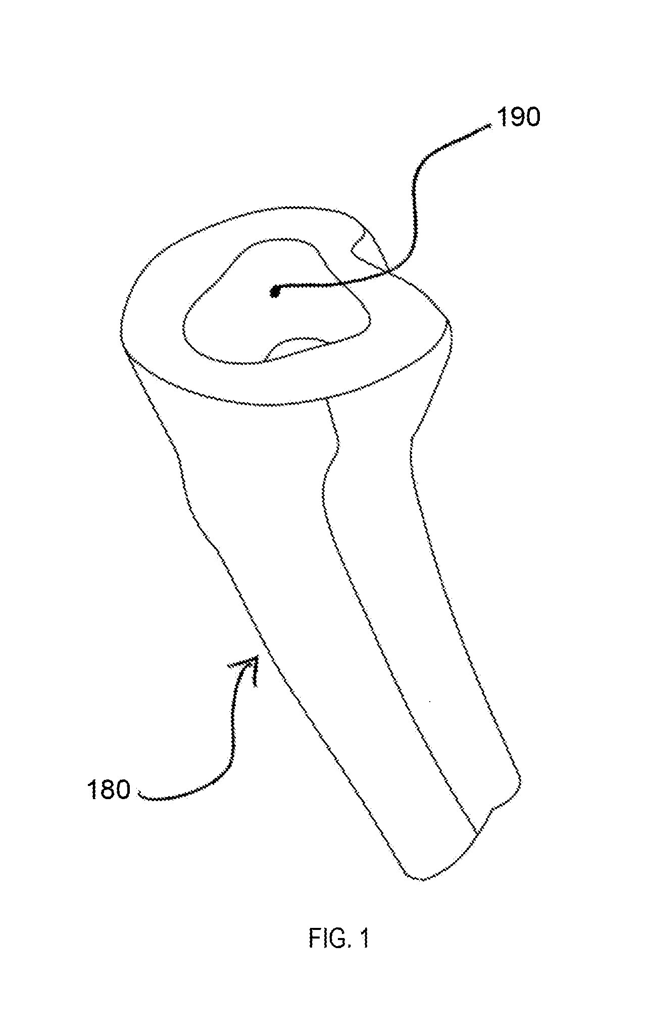
[0058]FIG. 1 shows a bone 180 having a canal 190. Bone 180 may be any type of bone, but as shown it represents a tibia of a patient. Canal 190 can be formed through a reaming procedure or may be present due to a previous joint replacement procedure in which a tibial prosthesis was implanted in canal 190 and has now been removed leaving a void in bone 180. Canal 190 can also be present because of bone degeneration such as osteoporosis. The present invention includes systems ...


PUM


Abstract

Disclosed herein are systems and methods for filling bone voids which may be present at the time of surgery. The systems disclosed herein generally include a baseplate component, a spacer component, and void filler component. The spacer component is generally assembled to the baseplate component with a taper or press-fit, for example, in one of a plurality of selected axial positions. The void filler component is then generally assembled to the spacer component in one of a plurality of selected axial positions. The void filler component preferably has an outer surface with portions having varying diameters such that the outer surface thereof can be received within a canal of a bone and contact the bone forming the canal at different locations in order to aid in stabilizing the assembled components in the canal.

Description

CROSS-REFERENCE TO RELATED APPLICATION[0001]This application claims the benefit of the filing date of U.S. Provisional Patent Application No. 61 / 364,070 filed Jul. 14, 2010, the disclosure of which is hereby incorporated herein by reference.FIELD OF THE INVENTION[0002]The present invention relates to joint prosthesis systems for filling voids in bones of a patient, and in particular it relates to assembling together the components of a joint prosthesis system in order fill a void in bone as needed and to properly position a support surface of the joint prosthesis system for receiving a corresponding prosthesis.BACKGROUND OF THE INVENTION[0003]Joint replacement surgery is a common orthopedic procedure for joint such as the shoulder, hip, knee, ankle and wrist. Prior to implanting prosthetic components in a joint of a patient, a surgeon generally has to resect at least a portion of the patient's native bone in order to create a recess or cavity for receiving at least a portion of the ...

Claims


Application Information

Patent Timeline
Patent Type & Authority Applications(United States)
IPC IPC(8): A61F2/30
CPCA61F2/30734A61F2/3886A61F2/389A61F2002/30884A61F2002/30405A61F2002/3054A61F2002/30354
Inventor MOORADIAN, MARKARNETT, JEFFERYBUTTERS, JOSHUA A.
Owner HOWMEDICA OSTEONICS CORP
Learn More