
Robotic heliostat system and method of operation

a robotic heliostat and heliostat technology, applied in solar heat systems, solar heat collector safety, light and heating apparatus, etc., can solve the problems of increasing the capital and maintenance costs of the total system by 40-50%, affecting so as to prolong the effective life of various onboard energy storage mechanisms, improve the efficiency of the system, and reduce the effect of maintenance costs

Inactive Publication Date: 2012-01-19
SOLARCITY
View PDF30 Cites 34 Cited by
  • Summary
  • Abstract
  • Description
  • Claims
  • Application Information

AI Technical Summary

Benefits of technology

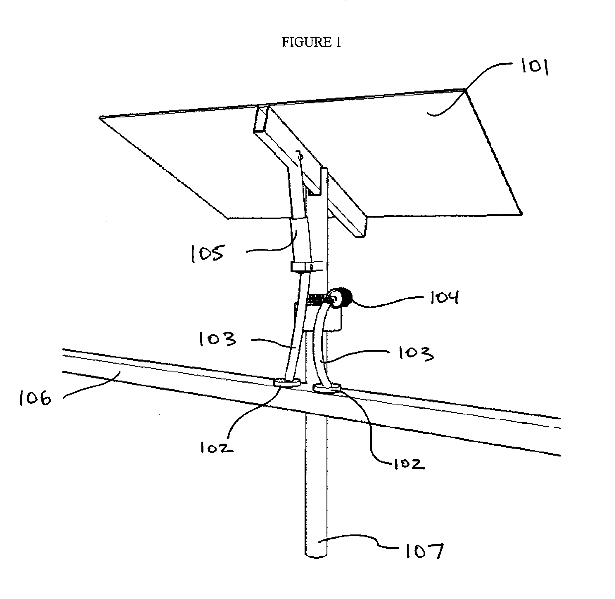
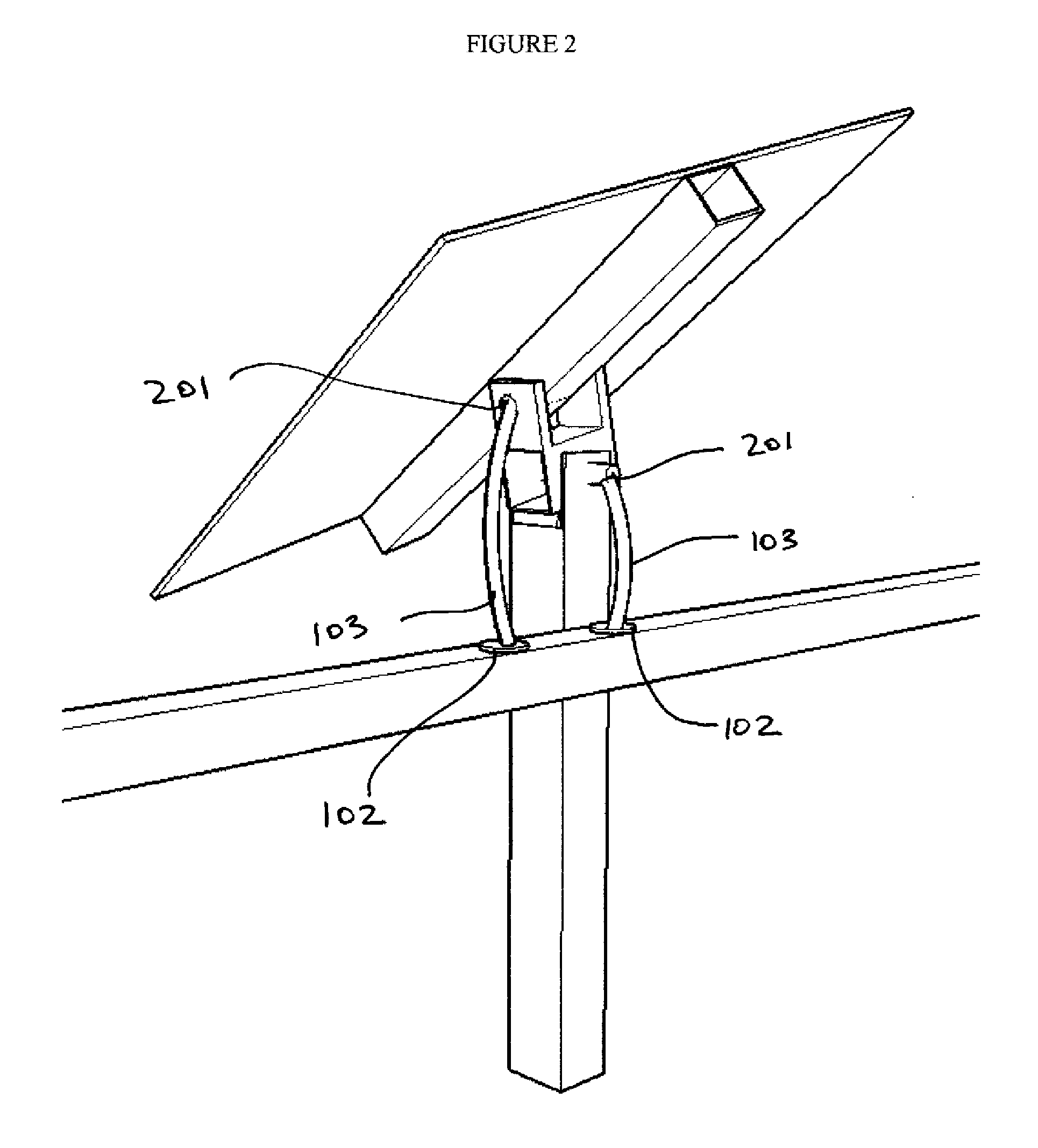
[0011]In an embodiment the invention can be used in conjunction with a heliostat or solar tracker that has its microprocessor, azimuth drive, elevation drive, central control system, and wiring removed. The elimination of these components allows for extreme cost reduction over conventional systems, and creates a fourth actuation paradigm: passive with active robotic control. In this model, a single robotic controller assumes the functional duties of calibrating and adjusting two or more solar surfaces in 3D space.
[0025]In a thirteenth embodiment the robotic controller can include an onboard climate control system that utilizes heat sinks, active cooling / heating systems, and moisture control mechanisms to maintain a constant temperature and environment for internal components. This system is particularly useful in extending the effective life of various onboard energy storage mechanisms.

Problems solved by technology

While this increase in energy production may seem attractive, current technology marginalizes the value of biaxial solar tracking by increasing total system capital and maintenance costs by 40-50%.
While control costs are reduced at this size, large trackers suffer from increased steel, foundational, and installation requirements.
While this effectively spreads out motor actuation costs, it places strict requirements on land grading, greatly complicates the installation process, and incurs a larger steel cost due to the necessary stiffness of the mechanical linkages.
Due to constant ground settling and imperfections in manufacturing and installation, heliostat and CPV systems require individual adjustments that increase system complexity and maintenance cost.
Passive systems utilizing hydraulic fluids, bimetallic strips, or bio-inspired materials to track the sun are limited to flat plate photovoltaic applications and underperform when compared to individually actuated or ganged systems.
Moreover, these systems are unable to execute backtracking algorithms that optimize solar fields for energy yield and ground coverage ratio.
The top and most expensive grade robotic controller may include all mechanisms necessary to precisely calibrate and adjust a field of solar surfaces.
If a single solar surface is rotated away from the sun, and the central power collection system detects no change in power output, the robotic controller may deem the solar surface to be defective.

Method used


Image

  • Robotic heliostat system and method of operation
  • Robotic heliostat system and method of operation
  • Robotic heliostat system and method of operation

Examples


Embodiment Construction

[0048]A preferred embodiment of the present invention is now described with reference to the figures where like reference numbers indicate identical or functionally similar elements. Also in the figures, the left most digits of each reference number corresponds to the figure in which the reference number is first used.

[0049]Reference in the specification to “one embodiment,”“a first embodiment,”“a second embodiment or to “an embodiment” (for example) means that a particular feature, structure, or characteristic described in connection with the embodiments is included in at least one embodiment of the invention. The appearances of the phrase “in one embodiment,”“a first embodiment,”“a second embodiment” or “an embodiment” (for example) in various places in the specification are not necessarily all referring to the same embodiment.

[0050]Some portions of the detailed description that follows are presented in terms of algorithms and symbolic representations of operations on data bits wi...


PUM


Abstract

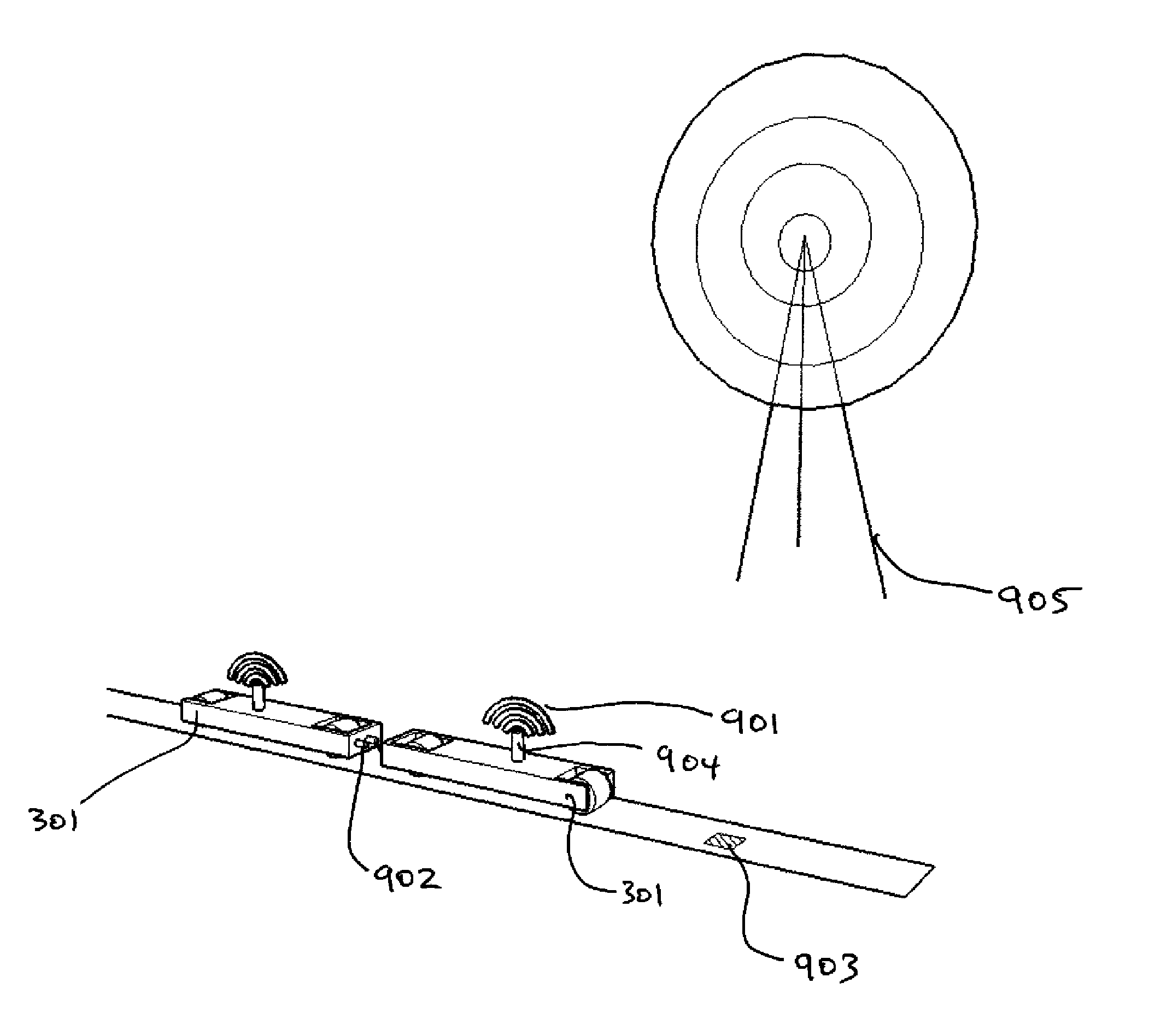
A system and method for operating a robotic controller to automatically position multiple solar surfaces in order to increase solar energy generation from the solar surfaces. In an embodiment the robotic controller travels in a sealed track and adjusts the solar surfaces using magnetic communication.

Description

RELATED APPLICATIONS[0001]This application claims priority from U.S. provisional application No. 61 / 364,729 filed on Jul. 15, 2010, and U.S. provisional application No. 61 / 419,685 filed on Dec. 3, 2010 which are all incorporated by reference herein in their entirety. This application is related to U.S. application Ser. No. 13 / 118,274 which is incorporated by reference herein in its entirety.FIELD OF THE INVENTION[0002]The present invention relates to solar tracking and calibration devices, and in particular tracking systems for photovoltaic, concentrated photovoltaic, and concentrated solar thermal systems that require constant repositioning to maintain alignment with the sun.BACKGROUND OF THE INVENTION[0003]In an attempt to reduce the price of solar energy, many developments have been made with respect to lowering the cost of precisely repositioning and calibrating a surface with two degrees of freedom. In concentrated solar thermal systems, heliostat arrays utilize dual axis repos...

Claims


Application Information

Patent Timeline
IPC IPC(8): F24J2/40F24J2/52F24S50/20
CPCF24J2/38F24J2/542Y02E10/47F24J2002/5462F24J2002/5441F24S2030/134F24S50/20F24S2030/115F24S30/452F24S40/52
Inventor TRUJILLO, SALOMONFUKUBA, DANIELCURRIER, THOMASBOKHARI, WASIQ
Owner SOLARCITY
Learn More