
Fixing device and image forming apparatus having the same

a technology of fixing device and image forming apparatus, which is applied in the direction of electrographic process apparatus, instruments, optics, etc., can solve the problems of reducing the warm-up time, consuming a considerable amount of electric power to generate heat, and fixing device may consume more than 50% of the entire amount of electric power consumption of image forming apparatus, so as to achieve the effect of strengthening the stiffness of the support elemen

Active Publication Date: 2012-01-12
HEWLETT PACKARD DEV CO LP
View PDF13 Cites 92 Cited by
  • Summary
  • Abstract
  • Description
  • Claims
  • Application Information

AI Technical Summary

Benefits of technology

[0012]The present general inventive concept provides a fixing device and an image forming apparatus having the same, which can reduce electric power consumption, reduce a warm-up time, and enhance a fixedness of a toner.
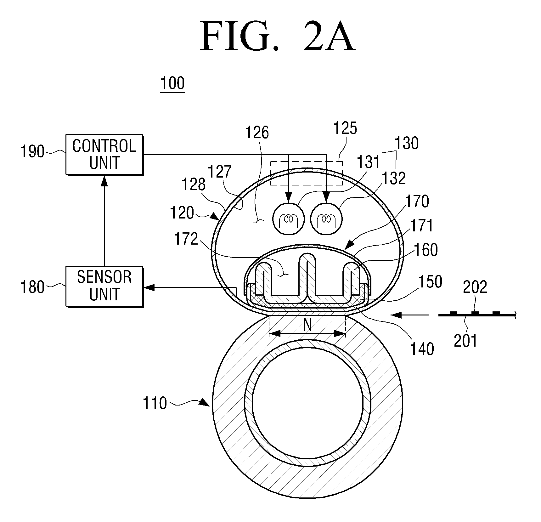
[0023]The fixing device may further include a reinforcement frame to reinforce a stiffness of the support element.

Problems solved by technology

Accordingly, the fixing device includes a heating unit, which consumes a considerable amount of electric power to generate the heat.
Actually, the fixing device may consume more than 50% of an entire amount of electric power consumption of the image forming apparatus.
Even though the image forming apparatus is turned on, the fixing device does not fix the unfixed toner immediately, and requires a warm-up time during which the fixing device reaches a temperature that effectively fixes the unfixed toner.
Since waiting for a warm-up time causes an inconvenience to a user, it is necessary to reduce the warm-up time.
In addition, if a fixedness of the toner is deteriorated, the toner may get on a user's hands when the print medium that finishes print process is rubbed with the user's hands.
Also, the present general inventive concept is not required to overcome the disadvantages described above, and an exemplary embodiment of the present general inventive concept may not overcome any of the problems described above.

Method used


Image

  • Fixing device and image forming apparatus having the same
  • Fixing device and image forming apparatus having the same
  • Fixing device and image forming apparatus having the same

Examples


Embodiment Construction

[0058]Exemplary embodiments of the present general inventive concept are described in greater detail below with reference to the accompanying drawings. In the following description, well-known functions or constructions are not described in detail but omitted if they would obscure the general inventive concept with unnecessary detail. Also, to assist in a comprehensive understanding of the general inventive concept, some elements may not be shown to scale, but be exaggerated in dimensions through the accompanying drawings.

[0059]Reference will now be made in detail to exemplary embodiments of the present general inventive concept, examples of which are illustrated in the accompanying drawings, wherein like reference numerals refer to the like elements throughout. The exemplary embodiments are described below in order to explain the present general inventive concept by referring to the figures.

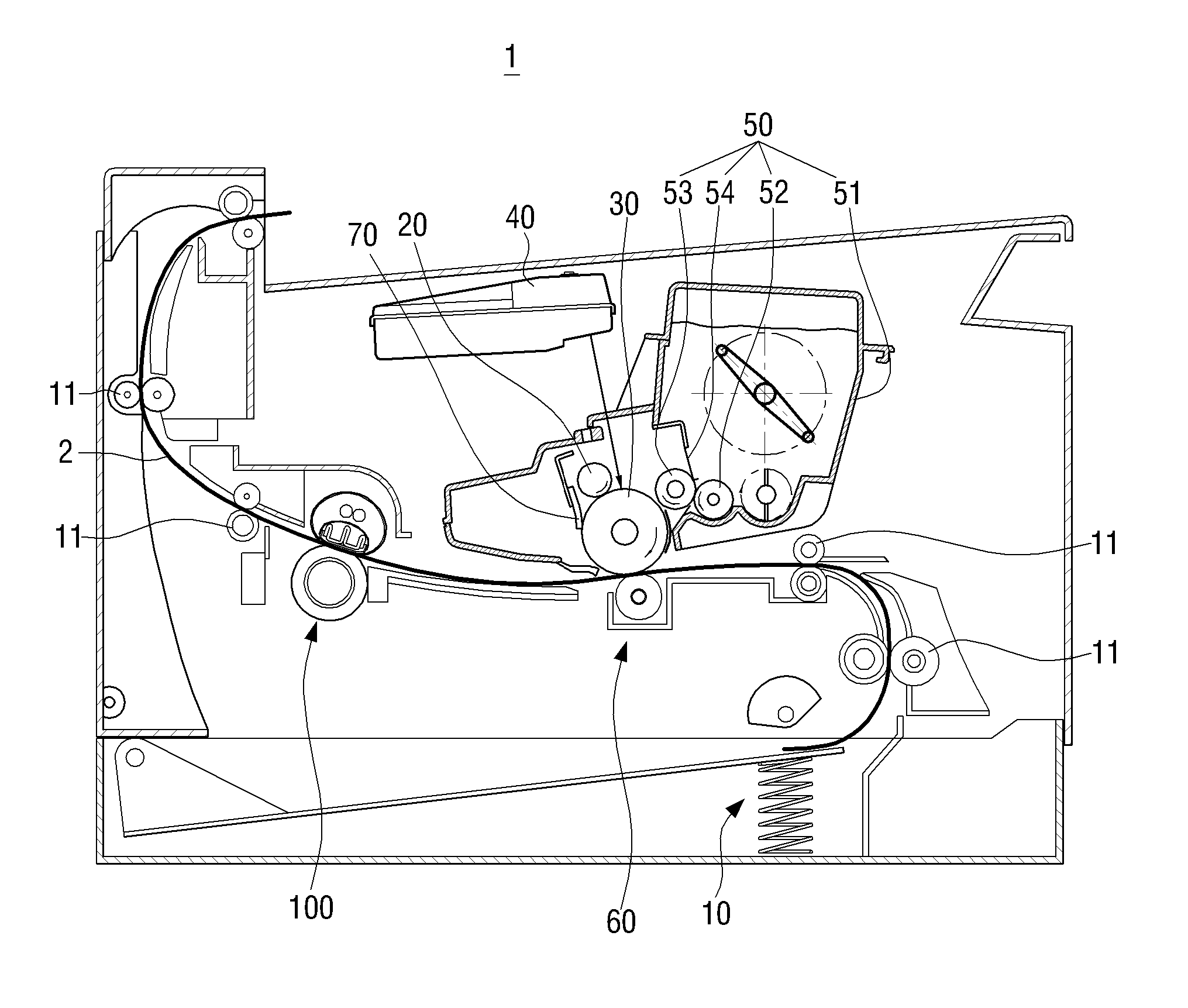
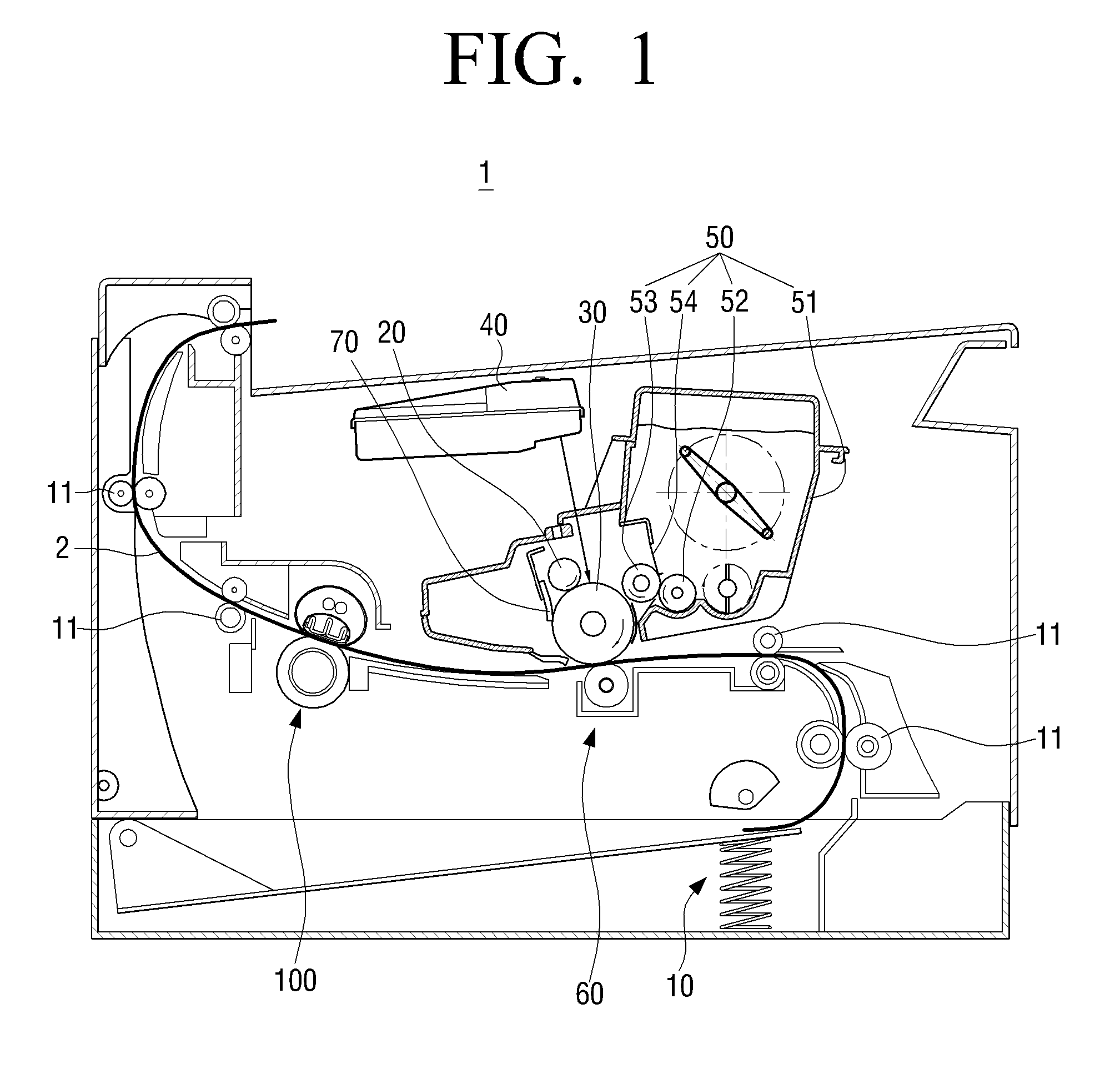
[0060]FIG. 1 is a view schematically illustrating an image forming apparatus 1 according to ...


PUM


Abstract

A fixing device includes a fixing belt to transmit a heat to a print medium, a pressing unit to apply a pressure on the print medium, a heating unit surrounded by the fixing belt to generate the heat and a nip plate disposed against the fixing belt and facing the pressing unit, to form a fixing nip. The fixing device further includes a support element to support the nip plate, and a reflection unit disposed within the fixing belt to reflect the heat radiated from the heating unit toward the support element. The reflection unit is connected to the nip plate to conduct the heat from the reflection unit to the nip plate.

Description

CROSS-REFERENCE TO RELATED APPLICATIONS[0001]This application claims priority under 35 U.S.C. §119(a) from Korean Patent Application No. 10-2010-66420, filed Jul. 9, 2010, in the Korean Intellectual Property Office, the disclosure of which is incorporated herein by reference in its entirety.BACKGROUND[0002]1. Field of the Invention[0003]Apparatuses consistent with the present general inventive concept relate to an image forming apparatus. More specifically, the present general inventive concept relates to a fixing device, which is used in the image forming apparatus.[0004]2. Description of the Related Art[0005]An image forming apparatus, such as a printer, a facsimile, a copier, a multifunction unit (MFU), or the like, forms an image on a print medium by using an electrophotography. In general, to form the image, the image forming apparatus performs an electric charging process, a light exposing process, an image developing process, an image transferring process, and an image fixing...

Claims


Application Information

Patent Timeline
Patent Type & Authority Applications(United States)
IPC IPC(8): G03G15/20
CPCG03G2215/2035G03G15/2064G03G15/2039G03G15/2053
Inventor LEE, JIN-SUNGKIM, SEONG-YUL
Owner HEWLETT PACKARD DEV CO LP
Learn More