
Three-phase common tank type gas insulated switchgear

a three-phase, gas-insulated switchgear technology, applied in switchgear arrangements, metal casing arrangements, gas-insulated enclosed substations, etc., can solve the problems of small current transformation ratio, poor accuracy class, and large size of current transformer units, so as to avoid the growth of size, reduce the overall scale of an integrated three-phase gis, and reduce the effect of manufacturing costs

Inactive Publication Date: 2012-01-05
JAPAN AE POWER SYST
View PDF7 Cites 2 Cited by
  • Summary
  • Abstract
  • Description
  • Claims
  • Application Information

AI Technical Summary

Benefits of technology

[0022]Configuring an integral three-phase GIS as the present invention defines permits to make the primary of the current transformer of each of the current transformer unit be a two-turn winding easily. Therefore, the ring iron core that constitutes the main section of current transformer can be small-sized with an advantage of avoiding growth in size. Thus, it becomes easy to provide the current transformer unit at the upper location and the lower location of the side surface of one vertical type tank. Accordingly, this brings such effects that the overall scale of an integrated three-phase GIS will be reduced and thereby that the manufacturing thereof is economical.

Problems solved by technology

This configuration leads to a small current transformation ratio accompanied by a poor accuracy class.
For improved electrical performance of a current transformer, it is unavoidably necessary to enlarge the size of the ring iron core, namely the main section of current transformer; this naturally causes the current transformer unit to become large in size.
As a consequence of this, it encounters problem such that an integrated three-phase GIS having a current transformer unit of such construction as is described above becomes large in scale or such that the constituting an integrated three-phase GIS having a built-in current transformer becomes difficult.
This technique however has included a problem in that increasing the number of turns is not an easily-attainable aim, because the current-carrying conductor (the primary coil) of a GIS, which conveys a large current, is usually a thick cylinder.

Method used


Image

  • Three-phase common tank type gas insulated switchgear
  • Three-phase common tank type gas insulated switchgear
  • Three-phase common tank type gas insulated switchgear

Examples


embodiment 1

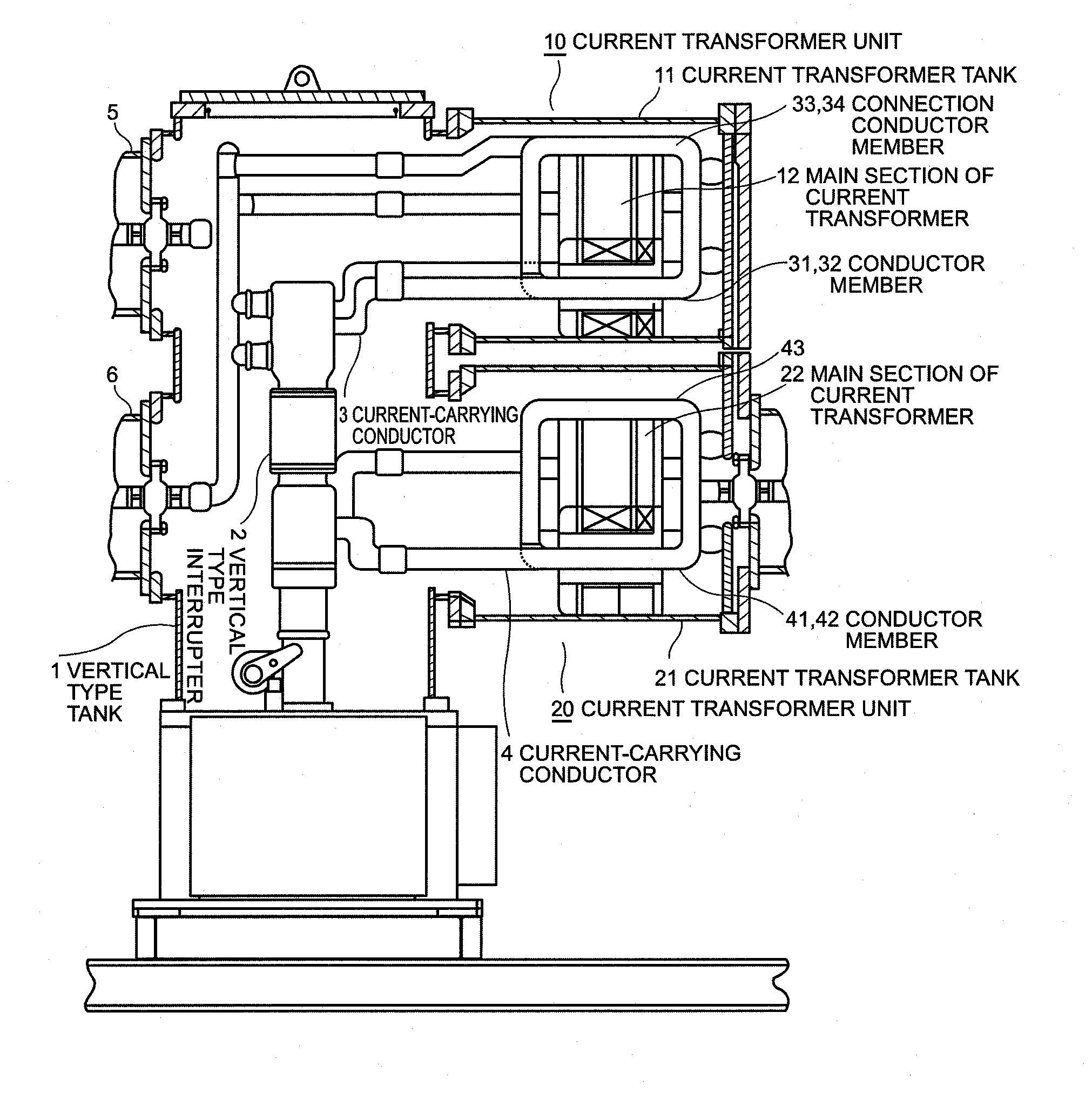
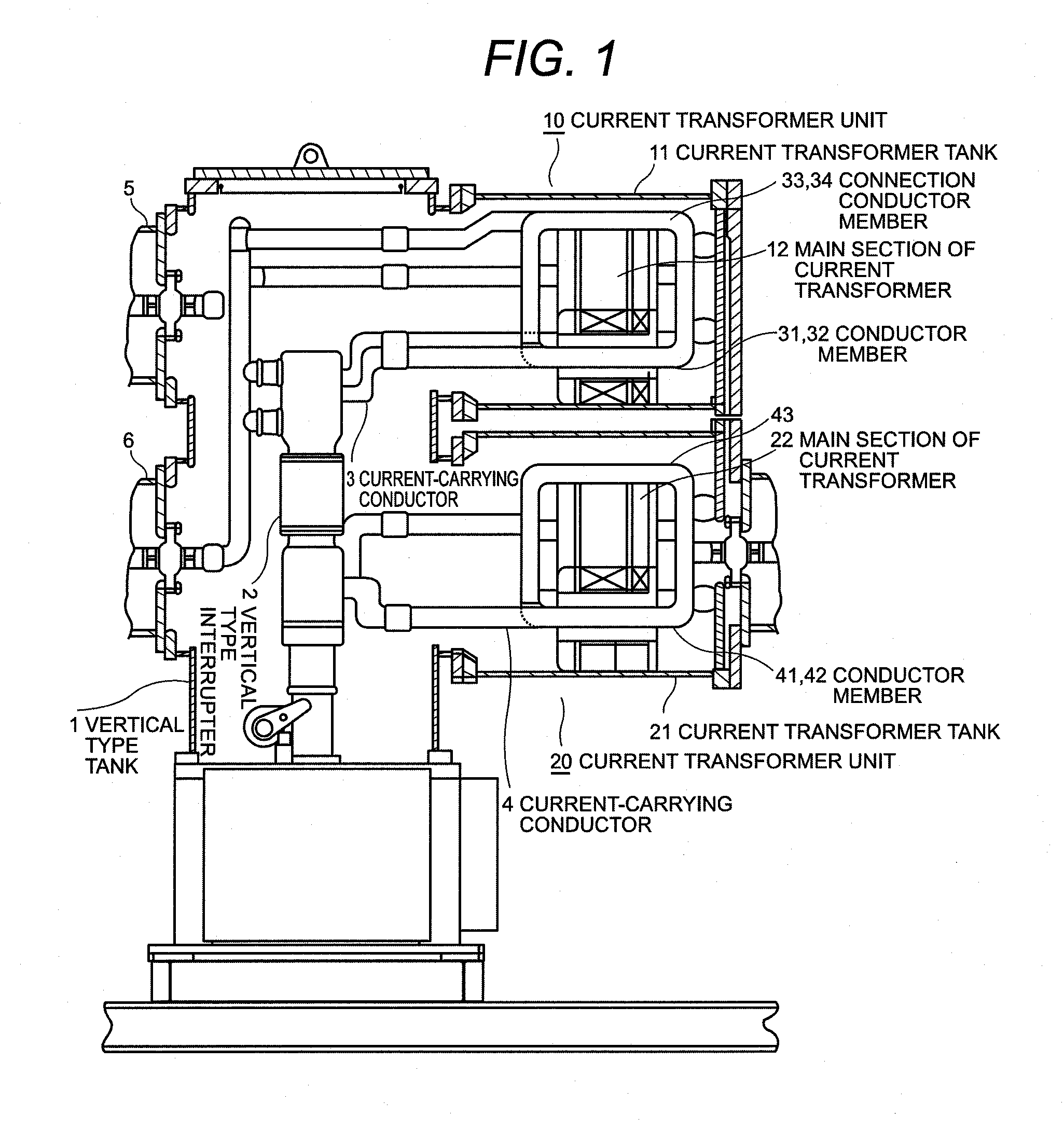
[0035]The following explains the integrated three-phase GIS by the present invention referring to FIG. 1 to FIG. 7 sequentially. In the integrated three-phase GIS illustrated in FIG. 1, vertical type interrupters 2, which makes current breaking, for three phases are arranged in rank formation in a vertical type tank 1 that is to be filled with insulating material and current carrying conductors 3 and 4 are connected respectively to the top end and the bottom end of each of vertical type interrupters 2. Similarly to conventional arts, the vertical type tank 1 has connections of main buses 5 and 6 of integral three-phase type at the upper location and the lower location of one surface thereof; an upper-located and a lower-located current transformer units 10 and 20 are provided respectively at the upper location and the lower location of the other side surface thereof.

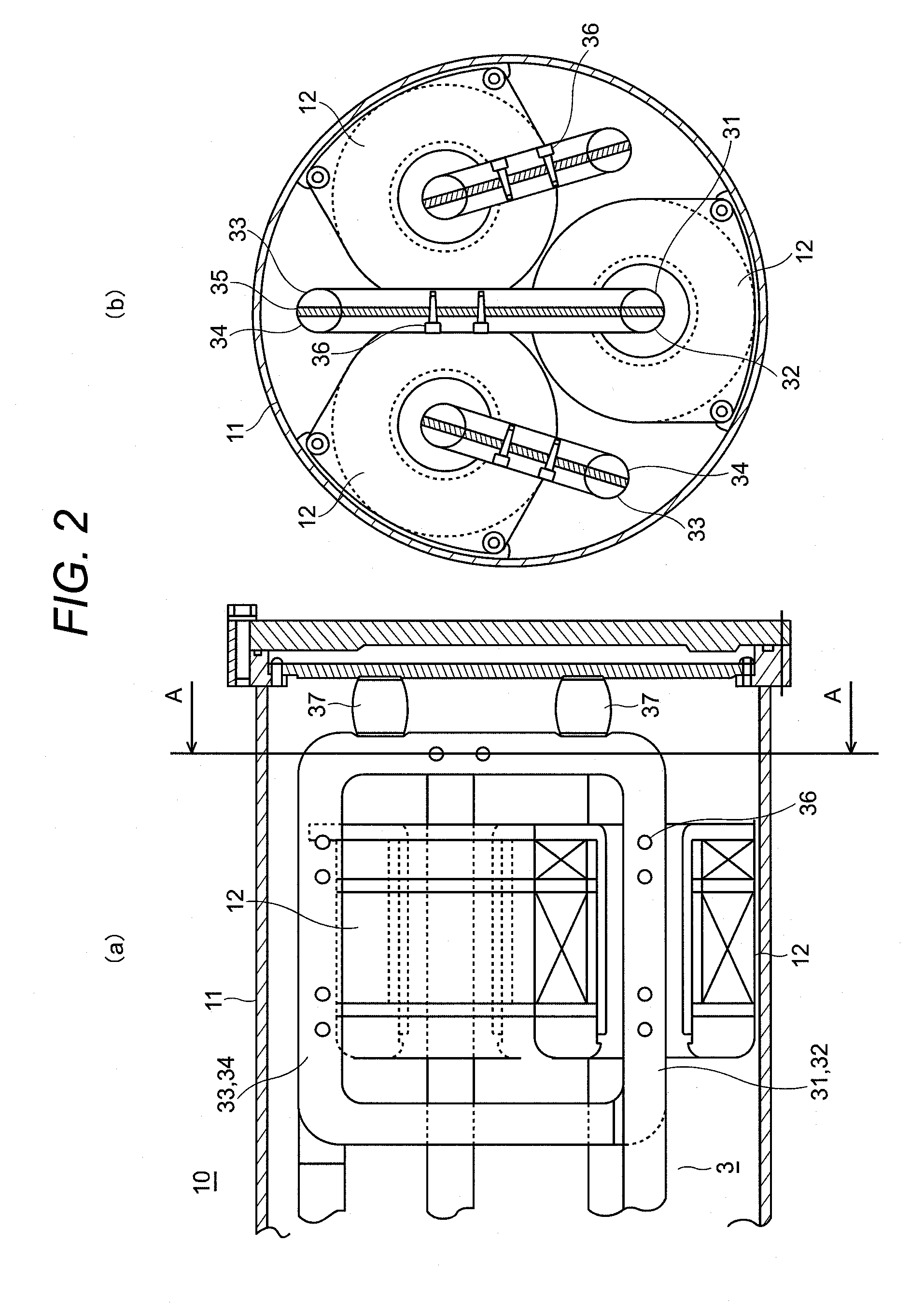
[0036]As illustrated in FIGS. 2(a) and 2(b) and FIGS. 5(a) and 5(b), the upper-located and the lower-located current t...

embodiment 2

[0052]Another embodiment of the present invention is illustrated in FIGS. 8 to 9 and FIGS. 10(a) to 10(d), which indicates another example of constitution of the current-carrying conductor 3 of the upper-located current transformer unit 10. The current-carrying conductor 3 of each phase has the first conductor member 31 having a cylindrical shape made of a hollow tube, the second conductor member 32 of a rod-phase placed concentrically inside the first conductor member 31 having the insulating material 35, and the connection conductor members 33 and 34 arranged having the insulating material 35 in a similar manner to the above.

[0053]The first conductor member 31 having a cylindrical shape and the second conductor member 32 of a solid bar are connected in series, as in the above-stated embodiment illustrated in FIGS. 2 and 5, by the connection conductor members 33 and 34 in a manner illustrated in FIG. 9 and FIGS. 10(a) to 10(d). The first conductor member 31 having a cylindrical sha...


PUM


Abstract

Vertical type tank 1, in which vertical type interrupters 2 for three phases are arranged, has current transformer units 10 and 20. Main sections of current transformer 12 and 22 for three phases are respectively arranged in current transformer units 10 and 20 so that the lines connecting their centers form triangle. Current-carrying conductors 3 and 4 connected to vertical type interrupter 2 are made to pass through main section 12 and 22, respectively. Each of current-carrying conductors 3 and 4 is connected to first and second conductor members 31, 41 and 32, 42, which pass through the main section and connected severally and respectively by connection conductor members 33, 34, and 43, so that the current path on the primary of the current transformer form a two-turn winding. Connection conductor members 33, 34 and 43 of each phase are arranged in the space between main section 12 and 22.

Description

TECHNICAL FIELD[0001]The present invention relates to a three-phase common tank type gas insulated switchgear, particularly to a three-phase common tank type gas insulated switchgear that has current transformer units in the upper location and the lower location of the side surface of its vertical type tank.BACKGROUND ART[0002]In general, a gas insulated switchgear (hereinafter referred to as a GIS) has electrical devices such as an interrupter, a disconnecting switch, and a current transformer; and connection conductors. These components are housed in a metallic container, which is filled with insulating material like sulfur hexafluoride (SF6) gas.[0003]The interrupter, which is the main part of an interrupter-setup arranged in the container, is used in a GIS in such a manner that one end of the interrupter is connected to a gas-insulated main bus through a current-carrying conductor and the other end thereof is connected to an insulated terminal such as a cable sealing end and a b...

Claims


Application Information

Patent Timeline
Patent Type & Authority Applications(United States)
IPC IPC(8): H02B7/01
CPCH02B13/0356H02B13/0352H02B13/02H02B13/035
Inventor INAMI, YOSHIAKIFUSJISAWA, CHIKARA
Owner JAPAN AE POWER SYST
Learn More