
Migration Velocity Analysis of Seismic Data Using Common Image Cube and Green's Functions

Inactive Publication Date: 2011-12-29
SAUDI ARABIAN OIL CO
View PDF3 Cites 40 Cited by
  • Summary
  • Abstract
  • Description
  • Claims
  • Application Information

AI Technical Summary

Benefits of technology

[0012]The present invention also provides a new and improved data storage device which has stored, in a computer readable medium, computer operable instructions for causing a data processing system to form a measure of the velocity of travel of seismic energy through subsurface formations from emission at a seismic energy source to reception at seismic energy receivers. The instructions stored in the data storage device cause the data processing system to assemble seismic data received at the receivers to form an array of common image data gathers as functions of cross-correlation lags and offset over depth levels of interest in the earth. The instructions also cause the data processing system to determine, from a selected seismic event of the assembled array of common image gathers which indicates a cross-correlation lag providing a maximum seismic energy focus, an amount of seismic energy travel time required to equalize upgoing and downgoing wavefields for the selected seismic event. The instructions cause the data processing system to repeat the step of determining an amount of seismic energy travel time for other seismic events in the assembled array of common image gathers, and form from the determined amounts of travel time for the seismic events in the array of common image gathers a velocity function indicating the seismic energy velocity for the depth levels of interest in the subsurface formations.

Problems solved by technology

This approach can be challenging in the presence of large velocity errors, as it may require many migration velocity analysis computer processing iterations before converging to a model that can accurately represent the events.
Building subsurface velocity models from seismic data remains one of the challenges in geophysics.
This is an ill-posed problem.
In the presence of complicated subsurface structures which are present in many regions, building an accurate model requires many processing iterations and considerable effort.
Data are typically contaminated with events that are not used in the velocity model scheme but rather mislead the process.

Method used


Image

  • Migration Velocity Analysis of Seismic Data Using Common Image Cube and Green's Functions
  • Migration Velocity Analysis of Seismic Data Using Common Image Cube and Green's Functions
  • Migration Velocity Analysis of Seismic Data Using Common Image Cube and Green's Functions

Examples


Embodiment Construction

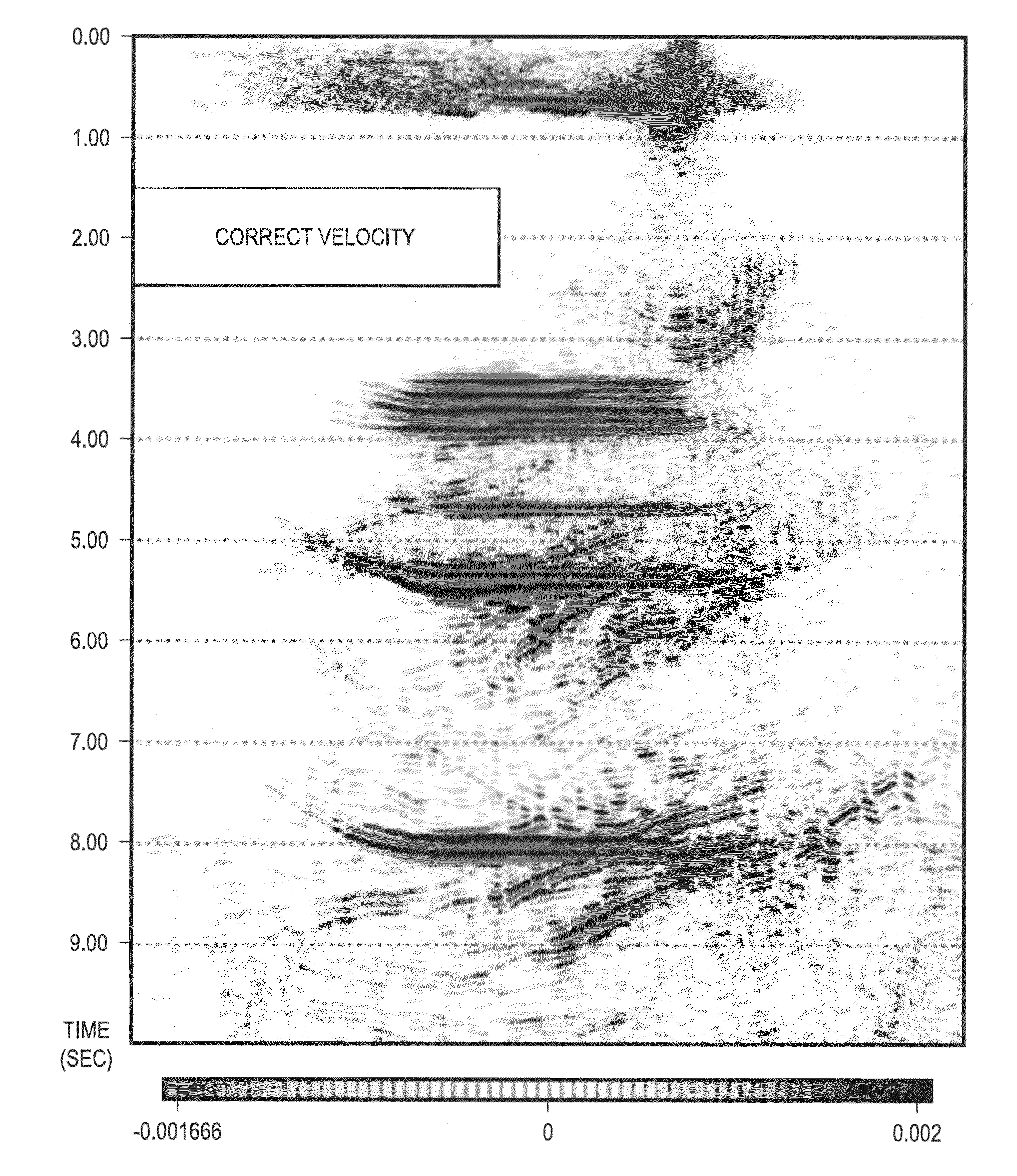
[0030]According to the present invention, a downward continuation based migration velocity analysis method is provided that can be used in structurally complex areas. This approach requires fewer migration velocity analysis iterations than conventional migration velocity analysis schemes and does not assume small velocity perturbations. The method of the present invention can also be used for target oriented migration velocity analysis, which is extremely useful for subsalt imaging. The technique is based on relaxing the cross correlation imaging condition that is typically used in shot profile migration. Instead of using only the zero lag cross correlation at each depth level, we retain other cross correlation lags are retained. The result, for a two dimensional dataset, is a three dimensional common image cube of migrated data that contains more prestack information than previous methods. Analyzing the data of the common image cube along a set of differing cross correlation lags, ...


PUM


Abstract

Seismic data are assembled and stored for a set of cross-correlation lag times to form an array of common image gathers over depth levels of interest. The two dimensional gathers assembled over different lag times form a three-dimensional cube of common image data. The data are analyzed to determine the travel time shift required to equalize upgoing and downgoing wavefields. Events in the common image gathers are then modeled using Green's functions to generate a data set representing the data resulting from processing had a precise velocity model been obtainable from the seismic data. The generated data are then processed with inversion techniques to form a velocity model for seismic data analysis.

Description

[0001]This application claims priority and benefit to U.S. Provisional Patent Application No. 61 / 359,583, by Al-Saleh, titled “Migration Velocity Analysis of Seismic Data Using Common Image Cube and Green's Functions” filed on Jun. 29, 2010, and which is incorporated herein by reference in its entirety.BACKGROUND OF THE INVENTION[0002]1. Field of the Invention[0003]The present invention relates to forming models of subsurface earth formations for seismic exploration and analysis.[0004]2. Description of the Related Art[0005]Seismic exploration involves the location of subsurface formations of interest for developing hydrocarbon production. Seismic data are obtained by imparting seismic energy to travel through the subsurface and recording the reflections of that energy which occur. The seismic data is then processed in computers so that the reflections or events, which occur at interfaces or boundaries between successive layers of formation rock, may be discerned and the data analyze...

Claims


Application Information

Patent Timeline
IPC IPC(8): G01V1/28G06G7/48G01V1/34
CPCG01V1/303G01V2210/1212G01V2210/1295G01V2210/675G01V2210/512G01V2210/6222G01V2210/1425
Inventor AL-SALEH, SALEH M.
Owner SAUDI ARABIAN OIL CO
Learn More