Eureka AIR delivers breakthrough ideas for toughest innovation challenges, trusted by R&D personnel around the world.

Easily unlatchable cam-lock actuating device for use in a locking coupling assembly that couples two tubular members

a technology of cam-lock and actuating device, which is applied in the direction of couplings, mechanical equipment, etc., can solve the problems of uncomfortable user grip and pulling of the pull ring 136

Active Publication Date: 2011-12-29
CHEN WATERSON
View PDF0 Cites 7 Cited by
  • Summary
  • Abstract
  • Description
  • Claims
  • Application Information

AI Technical Summary

Benefits of technology

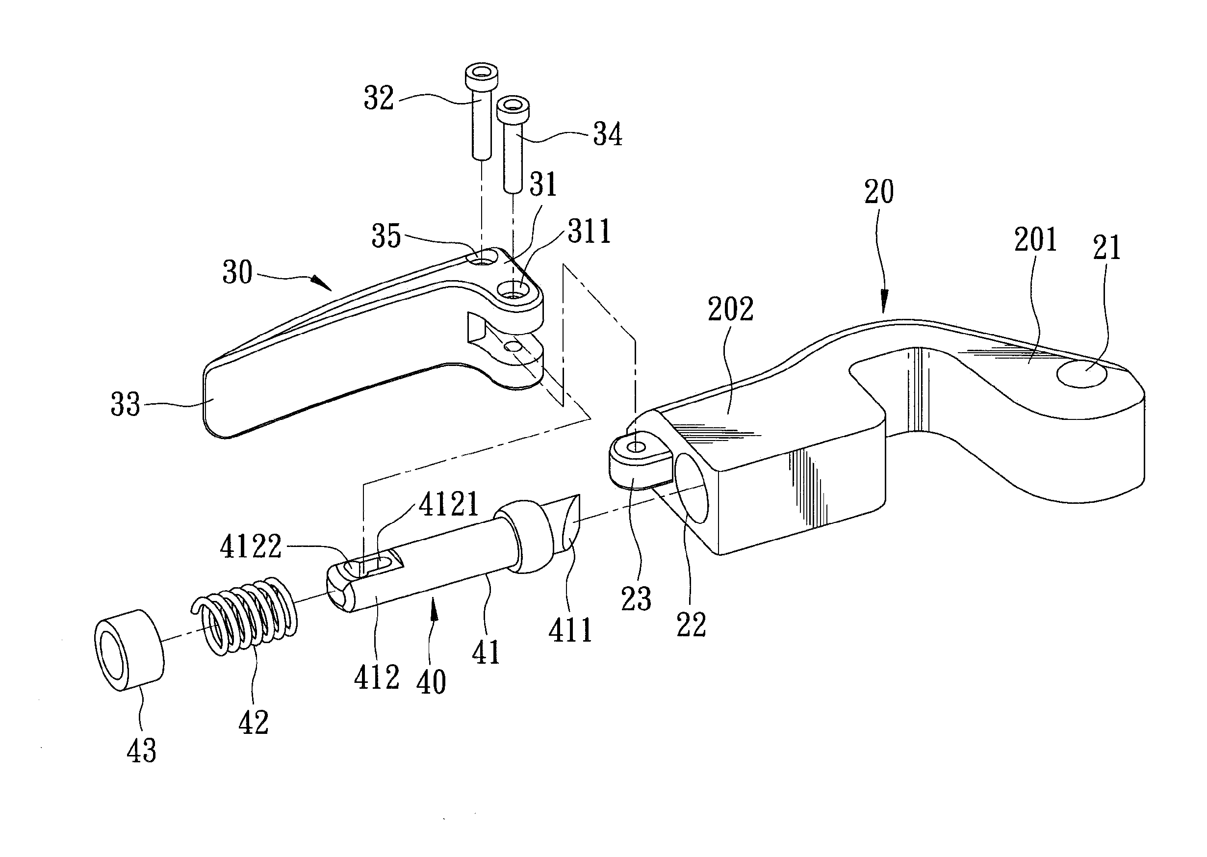
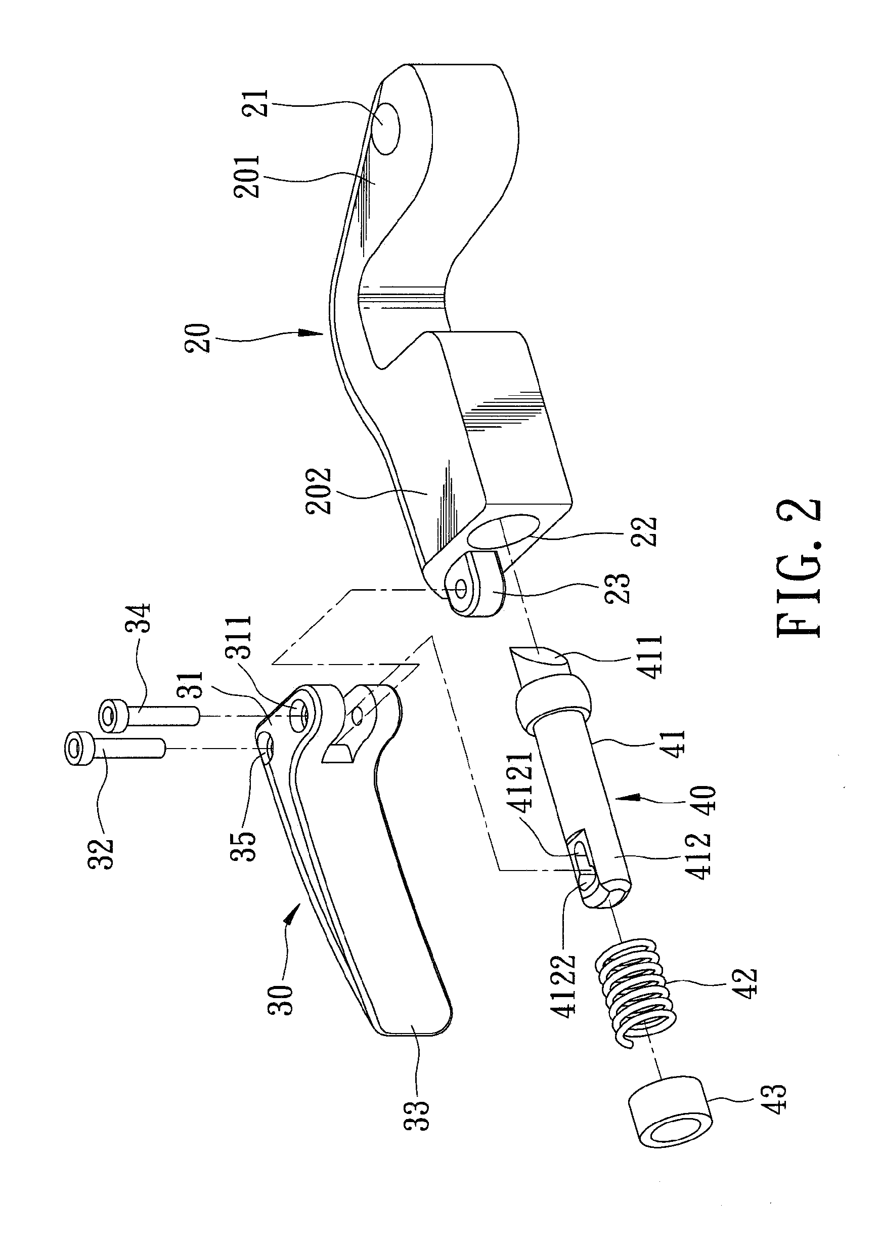
[0006]An object of the present invention is to provide an easily unlatchable cam-lock actuating device for use in a locking coupling assembly, which can be conveniently and comfortably operated to quickly connect and disconnect two tubular members.
[0011]Since the latch bolt is moved by operating the releasing lever, the locking and unlocking operations of the locking coupling assembly can be effortlessly and conveniently performed.

Problems solved by technology

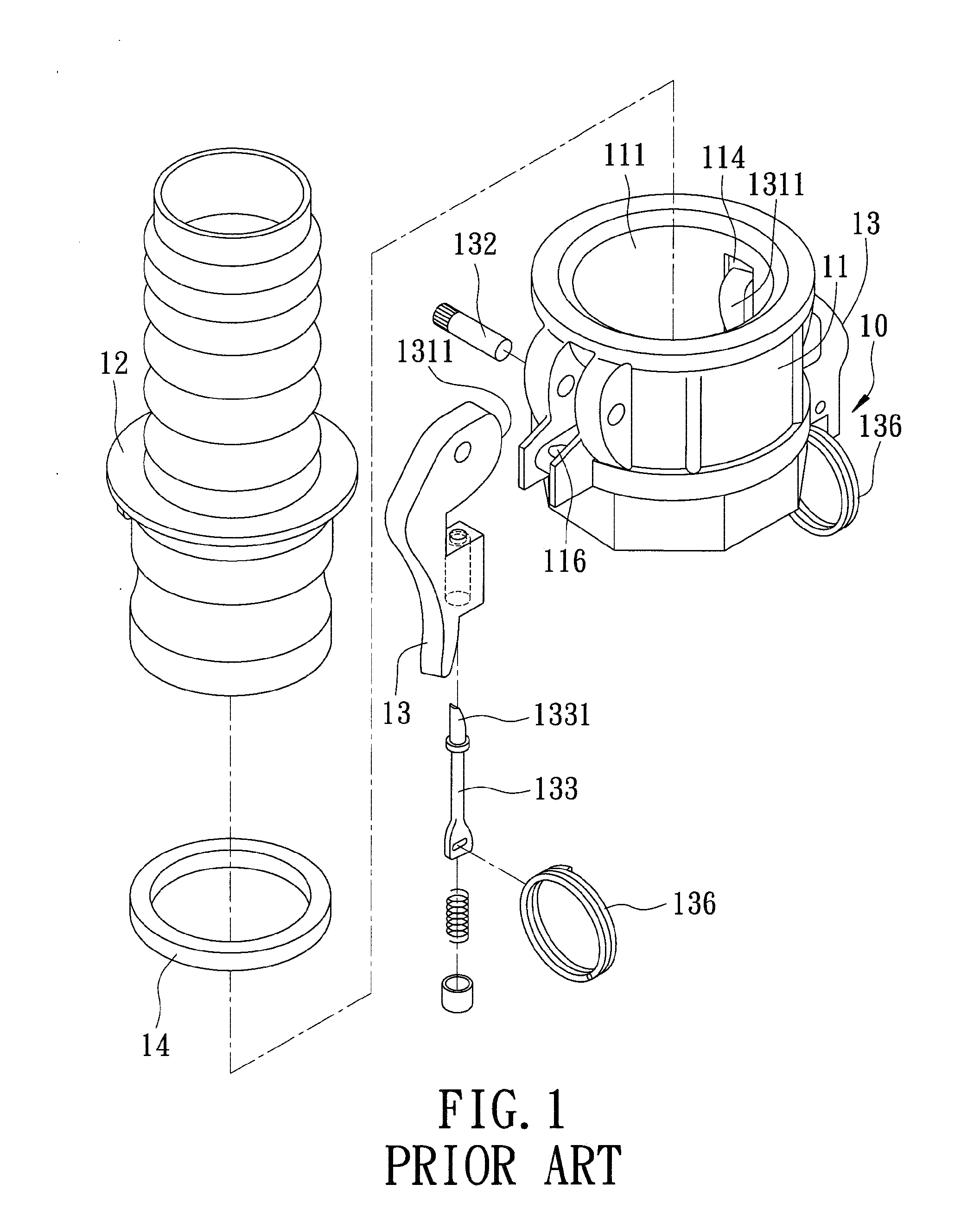
Moreover, gripping and pulling of the pull ring 136 is uncomfortable for the user since the pull ring 136 has a relatively small surface area.

Method used


Image

  • Easily unlatchable cam-lock actuating device for use in a locking coupling assembly that couples two tubular members
  • Easily unlatchable cam-lock actuating device for use in a locking coupling assembly that couples two tubular members
  • Easily unlatchable cam-lock actuating device for use in a locking coupling assembly that couples two tubular members

Examples


second embodiment

[0039]Referring to FIGS. 9 to 11, the second preferred embodiment of an easily unlatchable cam-lock actuating device according to this invention is similar to the previous embodiment in construction. In the second embodiment, the latch shank 41 has a pressed wall 413 which is spaced apart from the latch end 411 along the lengthwise line by a space 414. The weight end 31 of the releasing lever 30 is configured to extend into the space 414 to press the pressed wall 413 so as to permit the latch end 411 to be retracted and to be disengaged from the cavity 103 when the power end 33 is turned to the unlatched position, as shown in FIG. 12. In addition, the counter-force generating mechanism includes a retaining wall 24 which is disposed on the arm body 202 and which is spaced apart from the fulcrum axis 32, and a friction region 37 which is disposed on the releasing lever 30 and which is angularly displaced from the weight end 31 about the fulcrum axis 32 such that, as a result of displa...

third embodiment

[0040]Referring to FIGS. 13 to 16, the third preferred embodiment of an easily unlatchable cam-lock actuating device according to this invention is similar to the previous embodiments in construction. In the third embodiment, the weight end 31 of the releasing lever 30 includes a friction segment 312 extending from the fulcrum portion 35, and a pressing segment 313 which is pivotably mounted on the friction segment 312 by a pivot pin 38 about a turning axis parallel to the fulcrum axis 32, and which has a first cam surface 314. The latch shank 412 has a second cam surface 415 which mates with the first cam surface 314 such that, as shown in FIG. 17, turning of the power end 33 about the fulcrum axis 32 toward the unlatched position results in transverse movement of the pressing segment 313 relative to the lengthwise line to thereby permit the latch end 411 to disengage from the cavity 103. In addition, the counter-force generating mechanism includes a friction wall 315 which is disp...


PUM


Abstract

An easily unlatchable cam-lock actuating device for use in a locking coupling assembly that couples two tubular members, includes a cam arm pivotally mounted or a female tubular coupler and extending thereinto for locking a male tubular end of one of the tubular members, a spring-loaded latch bolt movably mounted in the cam arm to engage a cavity of the coupler so as to lock the cam arm at a locking position, and a releasing lever pivotally mounted on the cam arm and coupled to the latch bolt such that, when the releasing lever is turned from a latched position to an unlatched position, the latch bolt is retracted and disengaged from the cavity.

Description

BACKGROUND OF THE INVENTION[0001]1. Field of the Invention[0002]This invention relates to a locking coupling assembly that couples two tubular members, more particularly to an easily unlatchable cam-lock actuating device for use in a locking coupling assembly which is operable to quickly connect and disconnect two tubular members.[0003]2. Description of the Related Art[0004]Referring to FIG. 1, a conventional locking coupling assembly 10 disclosed in U.S. Pat. No. 5,435,604 is shown to include a cylindrical body 11 connected to a female coupling tube (not shown) , a male coupling tube 12 insertable into the cylindrical body 11, two cam arms 13 pivotably mounted on the cylindrical body 11 by pivot pins 132, and a seal ring 14 mounted on an inner surface of the cylindrical body 11. Each of the cam arms 13 has a cam surface 1311 extending through a slot 114 into a bore 111 in the cylindrical body 11 for engaging the male coupling tube 12 in the bore 111 when the cam arm 13 is at a lock...

Claims


Application Information

Patent Timeline
Patent Type & Authority Applications(United States)
IPC IPC(8): F16L37/18
CPCF16L37/18
Inventor CHEN, WATERSON
Owner CHEN WATERSON
Why Eureka
Eureka Blog
Learn More