
Tiltable Steering Wheel Apparatus for Work Vehicle

a technology for working vehicles and steering wheels, which is applied to steering parts, vehicle components, steering parts, etc., can solve the problems of difficult operation of manual control parts of control levers, difficulty in tilting the steering wheel to the desired position, and complicated construction, so as to improve operation efficiency, prevent extension or contraction, and simplify construction

Active Publication Date: 2011-12-29
KUBOTA LTD
View PDF3 Cites 14 Cited by
  • Summary
  • Abstract
  • Description
  • Claims
  • Application Information

AI Technical Summary

Benefits of technology

[0009]In view of the above circumstances, it is desired to provide a steering wheel apparatus which allows the seated operator to easily shift the steering wheel to a desired position.
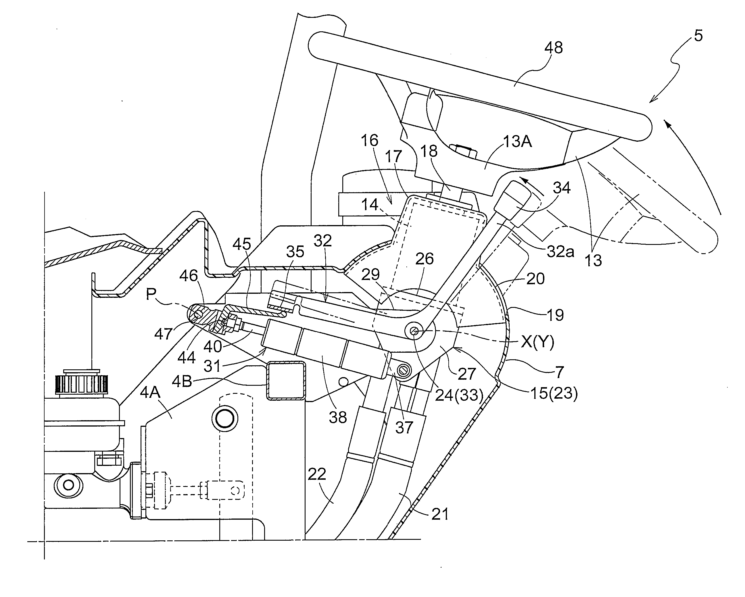
[0011]With the above arrangement, the seated operator easily operate the manual control portion of the control lever since the distance from the top surface of the grip portion to the swing axis extending along the rotational axis does not exceed the distance corresponding to the outer-diameter dimension of the grip portion centered on the rotational axis. Further, it is possible for the operator to operate the manual control portion of the control lever with one hand holding the grip portion of the steering wheel, with both hands holding the grip portion. This arrangement allows the operator to easily operate the manual control portion of the control lever and to tilt the steering wheel with both hands, as a result of which the seated operator may easily shift the steering wheel to a desired position.
[0013]According to another preferred embodiment of the present invention, the swing axis is coaxial with the pivotal axis. This arrangement allows a space to be easily secured between the steering wheel and the driver's seat and prevents the swing axis of the control lever from being relatively moved with the steering wheel in tilting the steering wheel. This improves the operational efficiency. Further, it becomes quite easy to arrange the control lever and the steering wheel to prevent the swinging operation of the control lever from interfering with the tilting operation of the steering wheel.
[0014]According to a further preferred embodiment of the present invention, the steering wheel support member has a steering wheel support base for rotatably supporting the steering wheel, and a support shaft for pivotably supporting the steering wheel support base about the pivotal axis, the support shaft also acting as the lever support member. With this arrangement, since the support shaft for pivotably supporting the steering wheel support base also acts as the lever support member, the control lever is swingably supported about the pivotal axis of the steering wheel. This further simplifies the construction. In addition, the control lever is assembled to be swingably operable about the swing axis that is coaxial with the pivotal axis more easily than the arrangement in which the lever support member is formed by a separate support shaft other than the support shaft for the steering wheel support base.
[0015]According to a still further preferred embodiment of the present invention, the tilting mechanism includes an extendable and contractable fluid-pressure cylinder for allowing tilting movement of the steering wheel, and the control lever is switchable between the tilting allowing mode for allowing extension or contraction of the fluid-pressure hydraulic cylinder and the tilting preventing mode for preventing extension or contraction of the fluid-pressure hydraulic cylinder. The fluid-pressure cylinder is mounted in the interior of a dashboard provided forwardly of a driver's seat. With this arrangement, it is possible to switch the state between the tilting allowing mode for allowing extension or contraction of the fluid-pressure hydraulic cylinder to allow tilting movement of the steering wheel and the tilting preventing mode for preventing extension or contraction of the fluid-pressure hydraulic cylinder to inhibit tilting movement of the steering wheel. The position of the steering wheel defined by its tilting movement about the pivotal axis is selectable in a stepless way to fix the steering wheel to a desired position. In addition, the fluid-pressure cylinder is mounted in the interior of the dashboard provided forwardly of the driver's seat and thus less visible from the driver's seat, which improves the external appearance.
[0016]According to a still further preferred embodiment of the present invention, the fluid-pressure cylinder includes a switching mechanism for switching the fluid-pressure cylinder between a position for preventing extension or contraction and a position for allowing extension or contraction, the switching mechanism being urged to switch from the position for allowing extension or contraction to the position for preventing extension or contraction, and the control lever is configured to operate the switching mechanism against an urging force to be switchable to the position for allowing extension or contraction. With this arrangement, the switching mechanism is operated against the urging force to be switched to the position for allowing extension or contraction by a manual swingable operation of the control lever first. When the manual swingable operation of the control lever is released, the switching mechanism is switched to the position for preventing extension or contraction by the urging force, and thus the steering wheel can be easily adjusted to the desired position.

Problems solved by technology

When the seated operator shifts the steering wheel to the desired position with such a steering wheel apparatus, the manual control portion of the control lever is difficult to operate because the manual control portion is swingably provided in a position lower than the pivotal axis of the steering wheel.
Moreover, the operator needs to rotate the steering wheel with one hand and thus may feel difficulty in tilting the steering wheel to the desired position.
Still further, since the swing axis of the control lever is moved relative to the steering wheel when the steering wheel is tilted, the control lever and the steering wheel need to be arranged to prevent a pivotal operation of the control lever from interfering with a tilting operation of the steering wheel, which may result in a complicated construction.

Method used


Image

  • Tiltable Steering Wheel Apparatus for Work Vehicle
  • Tiltable Steering Wheel Apparatus for Work Vehicle
  • Tiltable Steering Wheel Apparatus for Work Vehicle

Examples


Embodiment Construction

[0027]The embodiments of the present invention will be described hereinafter in reference to the accompanying drawings.

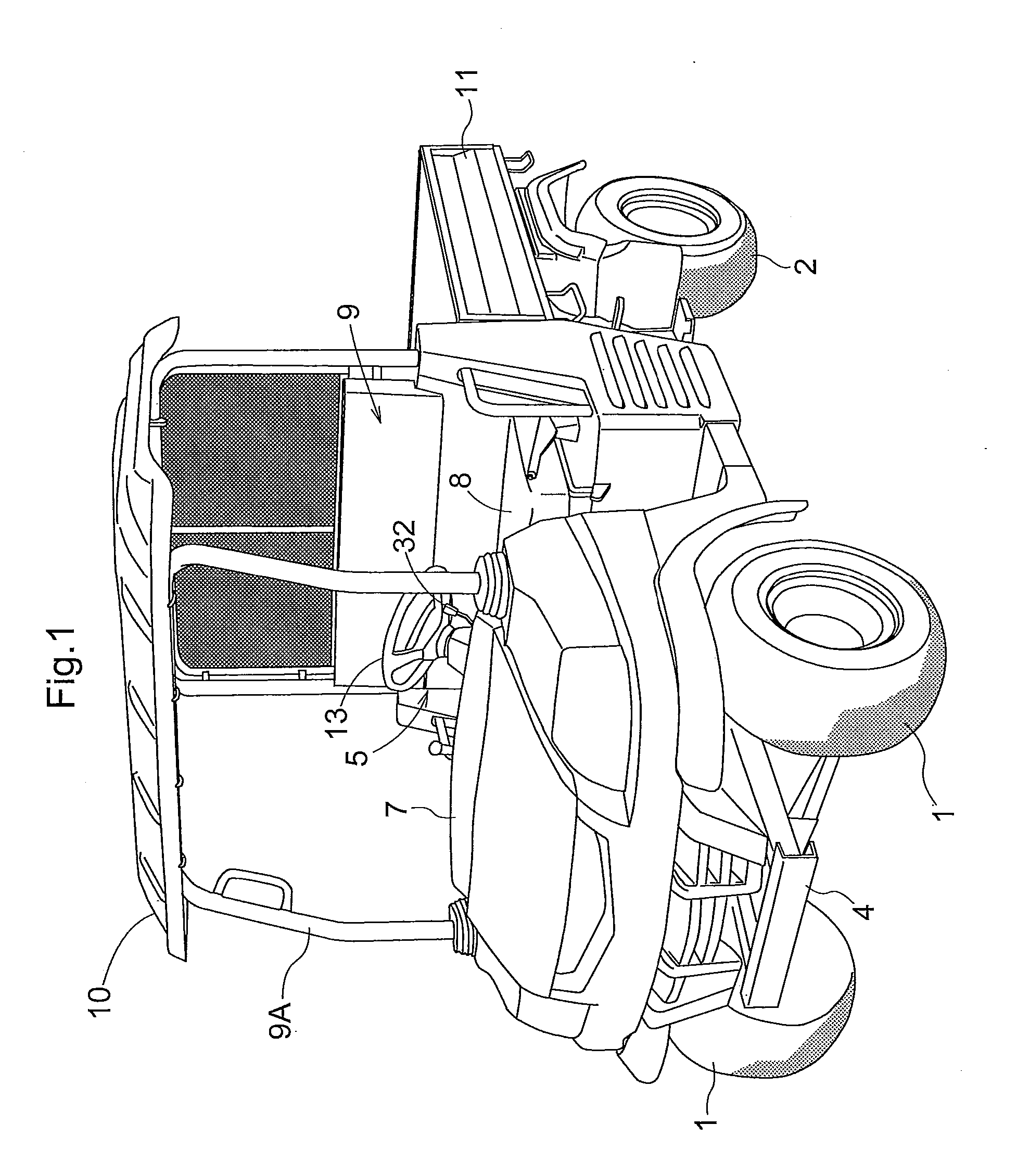
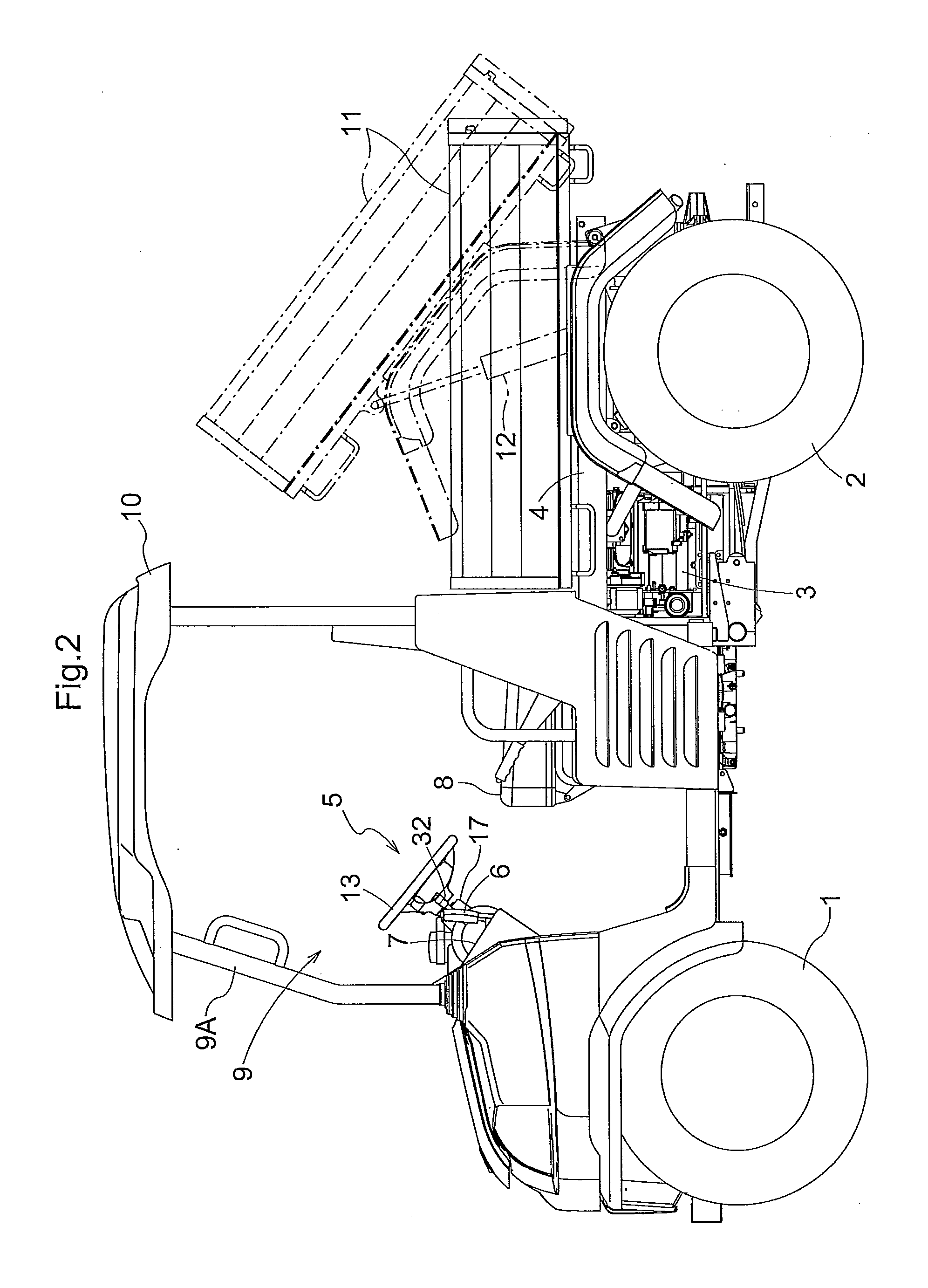
[0028]FIGS. 1 and 2 show a work vehicle such as a UV (utility vehicle) equipped with a steering wheel apparatus according to the present invention. The work vehicle comprises a pair of steerable right and left front wheels 1, a pair of right and left rear wheels 2, and an engine 3 mounted between the front wheels and rear wheels for driving the front and rear wheels 1 and 2.

[0029]The work vehicle further comprises a hood provided in a forward portion of a vehicle frame 4. In a longitudinal mid portion of the vehicle frame 4 are provided a driver's section 9 including a steering wheel apparatus 5 of the present invention, a forward / backward drive switching lever 6, a dashboard 7, all of which are provided forwardly of a driver's seat 8, a driver's section frame 9A mounted upright from the vehicle frame 4, and a sunshade 10 provided at the top of the driver's section ...


PUM


Abstract

A tiltable steering wheel apparatus comprises a tilting mechanism provided under a grip portion of a steering wheel. The tilting mechanism includes a steering wheel support member for supporting the steering wheel to be tiltable about a pivotal axis extending along a transverse direction of a vehicle body, and a control lever switchable between a tilting allowing mode for allowing tilting movement of the steering wheel and a tilting preventing mode for preventing tilting movement of the steering wheel. The control lever has an extension extending toward the grip portion with a manual control portion provided in a distal end thereof to be operable with the fingers of the operator holding the grip portion of the steering wheel.

Description

TECHNICAL FILED[0001]The present invention relates to a tiltable steering wheel apparatus for a work vehicle comprising a rotatable steering wheel, and a tilting mechanism including a steering wheel support member for supporting the steering wheel to be tiltable about a pivotal axis extending along a transverse direction of a vehicle body, both of which are provided forwardly of a driver's seat. The tilting mechanism further includes a control lever switchable between a tilting allowing, mode for allowing tilting movement of the steering wheel and a tilting preventing mode for preventing tilting movement of the steering wheel, and a lever support member for pivotably supporting the control lever about a swing axis extending along the transverse direction of the vehicle body. Further, the steering wheel includes an annular grip portion to be rotatable about a rotational axis of the steering wheel.BACKGROUND ART[0002]The steering wheel apparatus for the work vehicle as noted above com...

Claims


Application Information

Patent Timeline
Patent Type & Authority Applications(United States)
IPC IPC(8): B62D1/187
CPCB62D1/187B62D1/184
Inventor NAKAMURA, NORIMIFUJIWARA, KOJIKITAGUCHI, HIROAKINADA, KOJI
Owner KUBOTA LTD
Learn More