
Belt-type continuously variable transmission

a continuously variable transmission and belt type technology, applied in the direction of instruments, mechanical equipment, gearing, etc., can solve the problem that the actual speed ratio (a belt winding position) cannot be accurately determined, and achieve the effect of reducing size, simple structure and accurately measuring the actual transmission ratio

Inactive Publication Date: 2011-12-22
TOYOTA JIDOSHA KK
View PDF8 Cites 10 Cited by
  • Summary
  • Abstract
  • Description
  • Claims
  • Application Information

AI Technical Summary

Benefits of technology

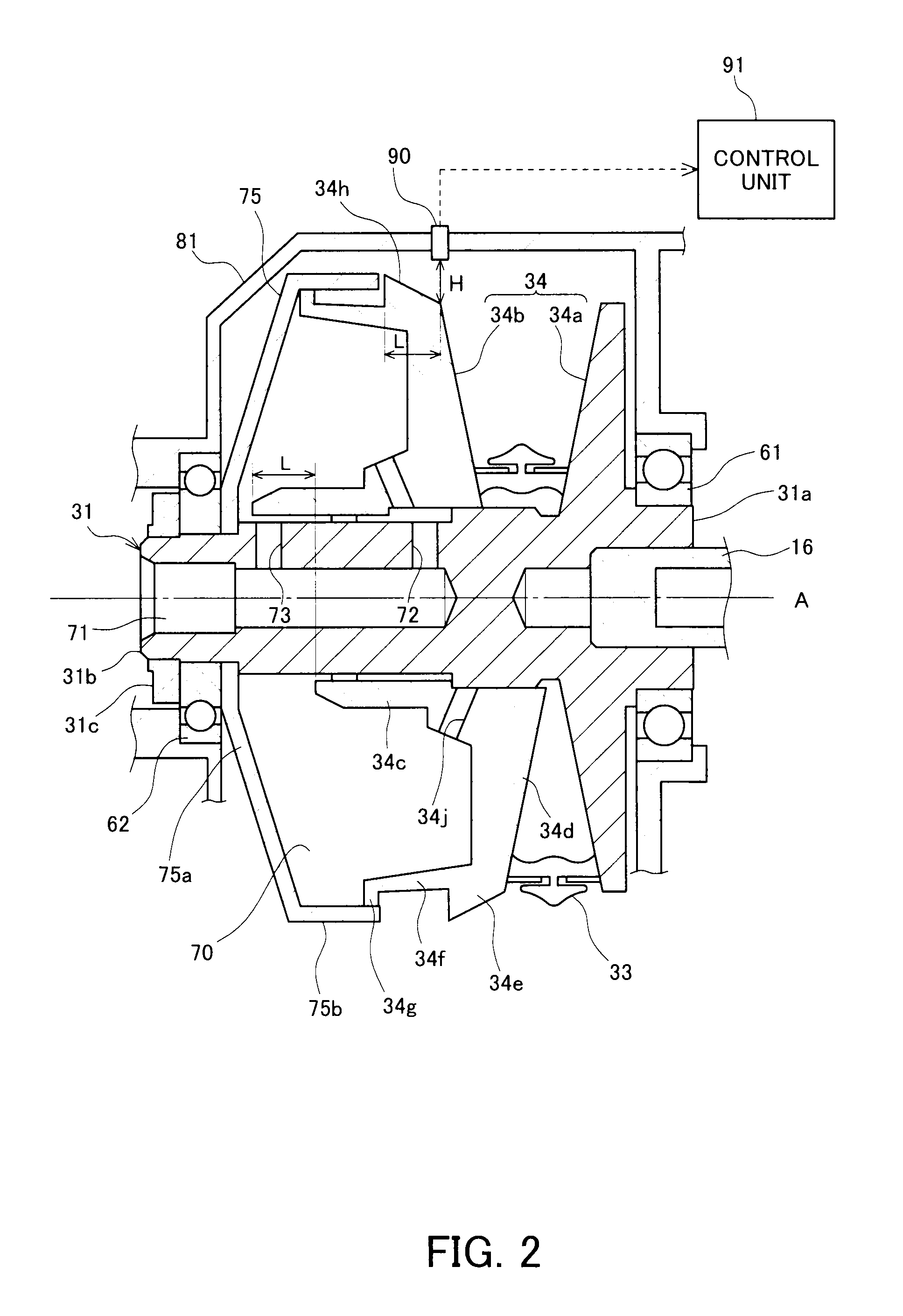
The present invention provides a belt-type continuously variable transmission with a movable sheave that changes the winding position of the belt to change the transmission ratio. A measurement surface is formed on the outer circumferential end of the movable sheave, and a displacement sensor measures the distance between the measurement surface and the sensor. This allows for the calculation of the winding position of the belt and the transmission ratio. The technical effect of this invention is to provide a more accurate and efficient continuously variable transmission for transmitting power between two objects.

Problems solved by technology

However, the number of rotations of each pulley determined may contain a transmission loss in a driving force due to belt slip or the like with respect to each pulley, and therefore there is a problem that the actual speed ratio (a belt winding position) cannot be accurately determined.

Method used


Image

  • Belt-type continuously variable transmission
  • Belt-type continuously variable transmission
  • Belt-type continuously variable transmission

Examples


Embodiment Construction

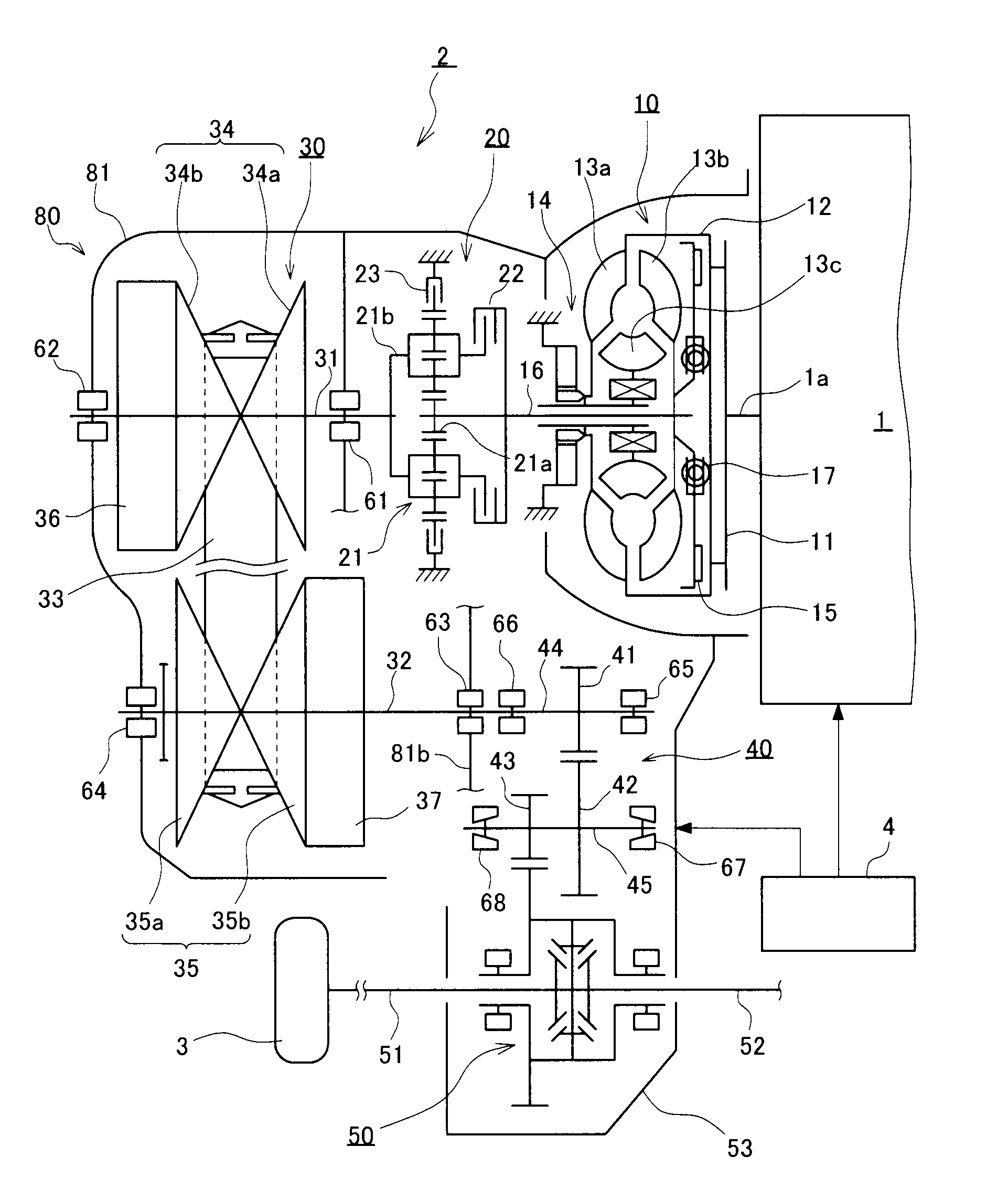
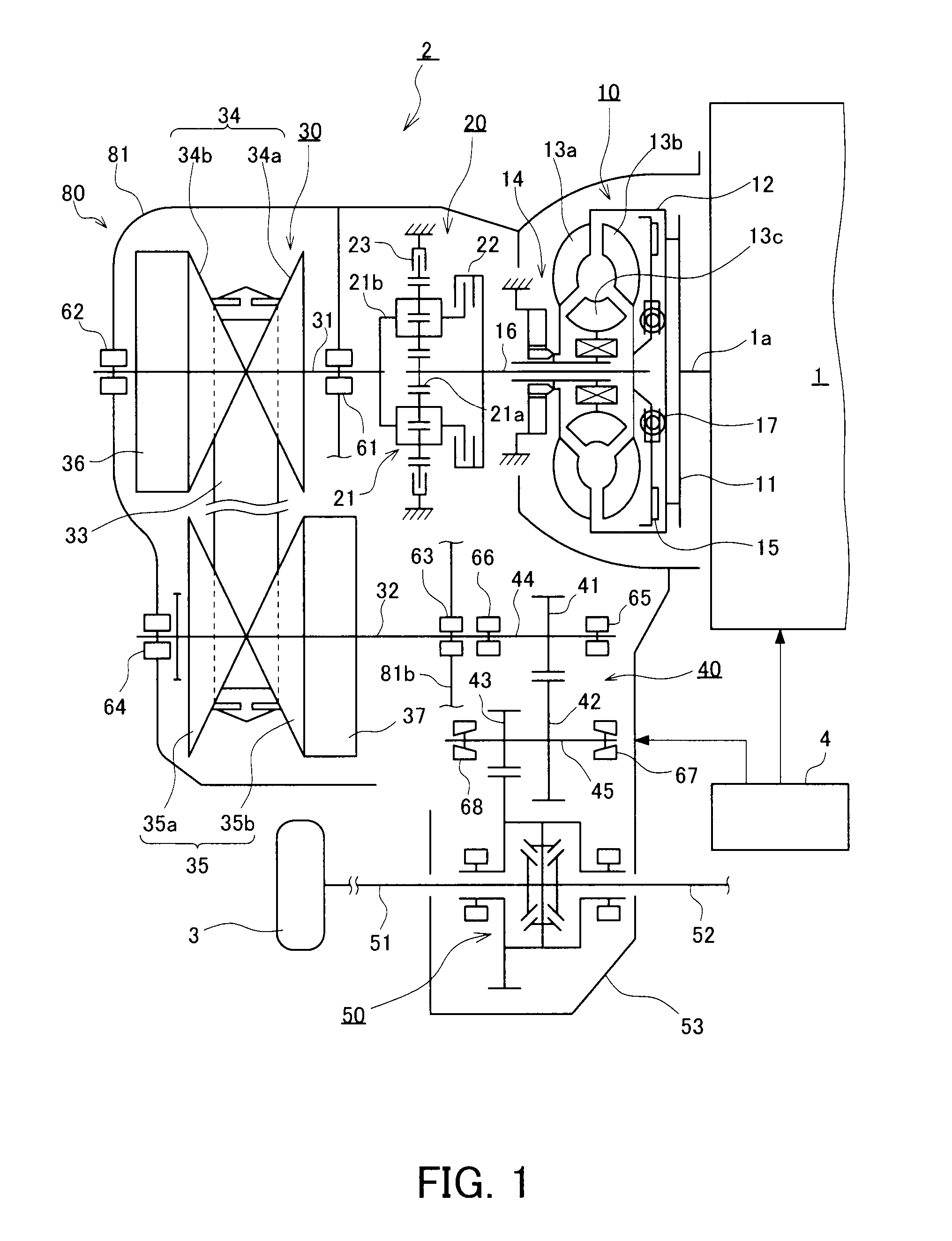
[0027]In the following, an embodiment of a belt-type continuously variable transmission according to the present invention will be described by reference to the drawings. In this embodiment, an automobile that is driven by an output from an engine will be referred to as an example, and a belt-type continuously variable transmission mounted in the automobile will be described. However, application of the present invention is not limited to a belt-type continuously variable transmission mounted in an automobile that is driven by an output from an engine, and the present invention can be applied to a belt-type continuously variable transmission mounted in an automobile that is driven by an output from a motor, such as, e.g., a hybrid vehicle or an electric vehicle.

[0028]Initially, a schematic structure of a vehicle carrying a belt-type continuously variable transmission 30 will be described by reference to FIG. 1. A vehicle has an engine 1 serving as a motor. The engine 1 is connected ...


PUM


Abstract

A belt-type continuously variable transmission that is able, using a simple structure, to accommodate size reduction and to accurately determine an actual transmission ratio. A belt-type continuously variable transmission includes a measurement surface formed on an outer circumferential end of a movable sheave, and a displacement sensor provided isolatedly from the outer circumferential end for measuring the distance between the measurement surface and the displacement sensor. The measurement surface is formed such that the distance H between the measurement surface and the displacement sensor is changed as the movable sheave moves in the axial direction.

Description

TECHNICAL FIELD[0001]The present invention relates to a belt-type continuously variable transmission, and in particular to improvement of a structure for determining a transmission ratio.BACKGROUND ART[0002]As a transmission connected on the output side of a motor for driving a vehicle, a belt-type continuously variable transmission (a so-called “CVT”: Continuously Variable Transmission) has been conventionally known.[0003]Such a belt-type continuously variable transmission comprises a primary shaft and a secondary shaft, which are two shafts mounted in parallel to each other, a drive side pulley mounted on the primary shaft, and a following side pulley mounted on the secondary shaft. The drive side and following side pulleys are each formed by combining a stationary sheave and a movable sheave opposed to the stationary sheave. Specifically, the stationary sheave is fixedly and integrally mounted on the outer circumference of a shaft, while the movable sheave is provided so as to ap...

Claims


Application Information

Patent Timeline
Patent Type & Authority Applications(United States)
IPC IPC(8): G06F15/00
CPCF16H9/18F16H55/56F16H63/065F16H61/66259F16H59/70
Inventor YAMAGUCHI, KENICHI
Owner TOYOTA JIDOSHA KK
Learn More