
System and method for optimizing use of a battery

a battery and optimization system technology, applied in the field of battery optimization system, can solve the problems of drive consuming such a large amount of battery power, high cost, and needing full charge, and achieve optimal charging/discharging cycle, optimize the use of battery, and optimize the effect of battery us

Inactive Publication Date: 2011-12-22
TOYOTA MOTOR CO LTD
View PDF3 Cites 77 Cited by
  • Summary
  • Abstract
  • Description
  • Claims
  • Application Information

AI Technical Summary

Benefits of technology

"The invention is a battery optimization system and method for regulating and discharging a battery to optimize its use based on the user's preference. The system includes a power source, a charging / discharging station, and a controller in communication with the power source and / or charging / discharging station. The controller processes battery and power source information along with user input to calculate an optimal charging / discharging cycle. The optimal cycle is based on the user's preferences and can vary depending on the power source, user desires, and battery state. The invention can be used in electric vehicles that have a battery to assist with their actuation."

Problems solved by technology

The peak-rate is often more costly than other times as the power source has to pay for additional power to meet the power demand.
However, there may be instances where the user would rather pay a premium peak rate to charge their battery.
The drive may consume such a large amount of power from the battery that it is necessary for the driver to charge the battery while at work and again at night.
However, in some instances only one full charge is needed to support the drive to and from work.
As shown, a daily deep discharge and recharge cycle can significantly shorten the life of the battery.
However, small discharges and recharges will extend the life of the battery.
In some instances it may not be practical to charge the battery in accordance with a charging / discharging cycle that maximizes the life of the battery.
For instance, the battery's power may be low and the user may only have a relatively short period of time to charge the battery.

Method used


Image

  • System and method for optimizing use of a battery
  • System and method for optimizing use of a battery
  • System and method for optimizing use of a battery

Examples


Embodiment Construction

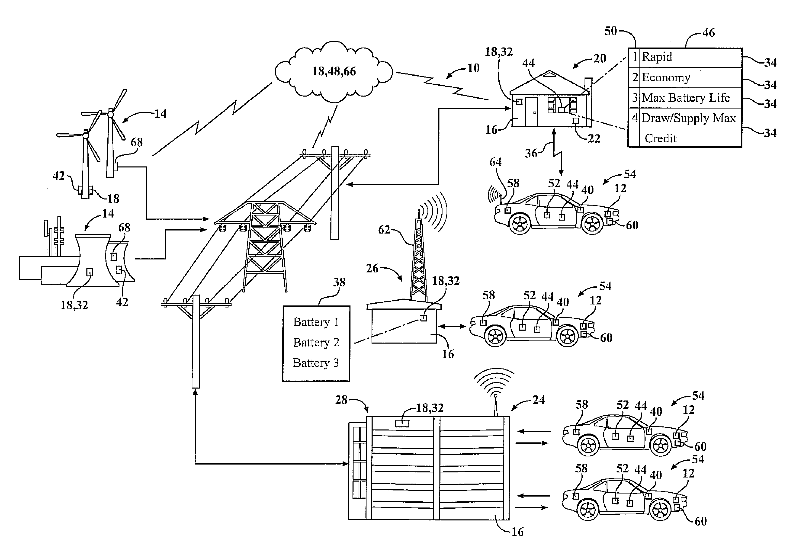
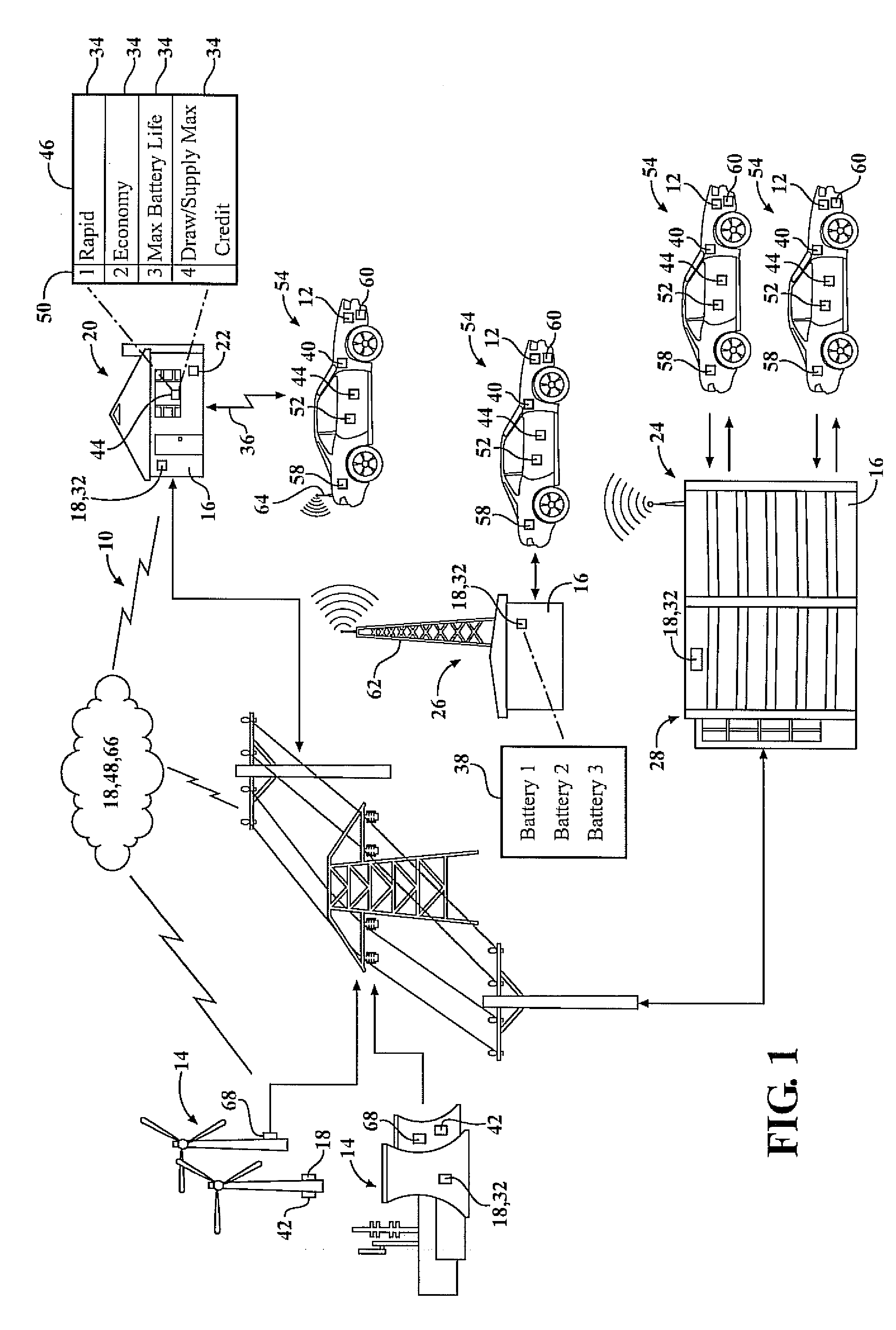
[0025]Referring to the figures, a battery optimization system 10 for regulating charging and discharging of a battery 12 so as to optimize the use of the battery 12 in accordance with a user's preference is provided. The battery optimization system 10 includes a power source 14, a charging / discharging station, “CD Station 16,” and a controller 18. The power source 14 may be a local power provider or a larger commercial power provider such as a publicly held utility company. The CD Station 16 connects the battery 12 with the power source 14. The CD Station 16 may be disposed in a residential house 20 and is in communication with a power outlet 22 such as a utility plug. The power outlet 22 may also be disposed in a workplace 24, or a public place 26 such as the parking lots of shopping malls and the like.

[0026]The controller 18 may be in communication with either the CD Station 16, power source 14, and / or the battery 12. The battery 12 may be a lithium-ion battery. Preferably, the ba...


PUM


Abstract

A battery optimization system and method for regulating and discharging a battery so as to optimize the use of the battery in accordance with the user's preference is provided. The battery optimization system includes a power source, a charging / discharging station connecting the battery with the power source, and a controller in communication with the charging / discharging station. The battery optimization system further includes an input operable to provide the user's preferences. The controller is also in communication with the battery and is operable to process battery and power source information along with user input to calculate an optimal charging / discharging cycle. The charging / discharging cycle is configured to charge or discharge the battery so as to optimize the use of the battery based upon the end user's preference. For instance, the calculated optimal charging / discharging cycle may be based upon the user's desire to maximize the life of the battery, or to charge the battery as inexpensively as possible.

Description

FIELD OF THE INVENTION[0001]The present invention relates to a battery optimization system for regulating the charging and discharging of a battery so as to optimize the use of the battery in accordance with the user's preference. The battery optimization system includes a controller operable to process information so as to calculate an optimal charging / discharging cycle. The battery optimization system also includes an input operable to provide user preferences. The controller is further operable to process user input, battery status and the state of the power source so as to charge or discharge the battery in accordance with the user's preference.BACKGROUND OF THE INVENTION[0002]The concept of drawing and supplying energy between a battery and a power grid is known. Such a concept when applied to a vehicle battery and power grid is commonly referred to as vehicle to grid / grid to vehicle (V2G / G2V). The vehicle battery draws power as needed and supplies power during times when the b...

Claims


Application Information

Patent Timeline
Patent Type & Authority Applications(United States)
IPC IPC(8): H02J7/00G06F17/00G06F7/00
CPCB60L11/184Y02T90/121B60L11/1848B60L11/185B60L11/1859G06Q50/06H01M10/44H01M10/48H02J7/0075H02J7/044Y02T10/7005Y02T10/705Y02T90/16Y02T90/169Y02T90/14Y02T90/128Y04S10/126Y04S30/14Y02E60/721B60L11/1842Y02T10/7072B60L53/64B60L55/00B60L53/665B60L53/11B60L58/14H02J7/00716H02J7/0069Y02E60/00Y02T10/70Y02T90/12Y02T90/167Y02E60/10H02J7/04
Inventor LABERTEAUX, KENNETH P.GULASH, CHARLES E.
Owner TOYOTA MOTOR CO LTD
Learn More