
Green electric vehicle utilizing multiple sources of energy

a technology of electric vehicles and renewable energy, applied in the field of vehicles, can solve the problems of dire consequences for the environment, large number of batteries, and inability to connect the permanent connection of electric motors to electrical power supply lines, and achieve the effects of destroying the environment, affecting human and animal life, and affecting the environmen

Inactive Publication Date: 2011-12-22
HASSAN M HASSAN
View PDF14 Cites 44 Cited by
  • Summary
  • Abstract
  • Description
  • Claims
  • Application Information

AI Technical Summary

Benefits of technology

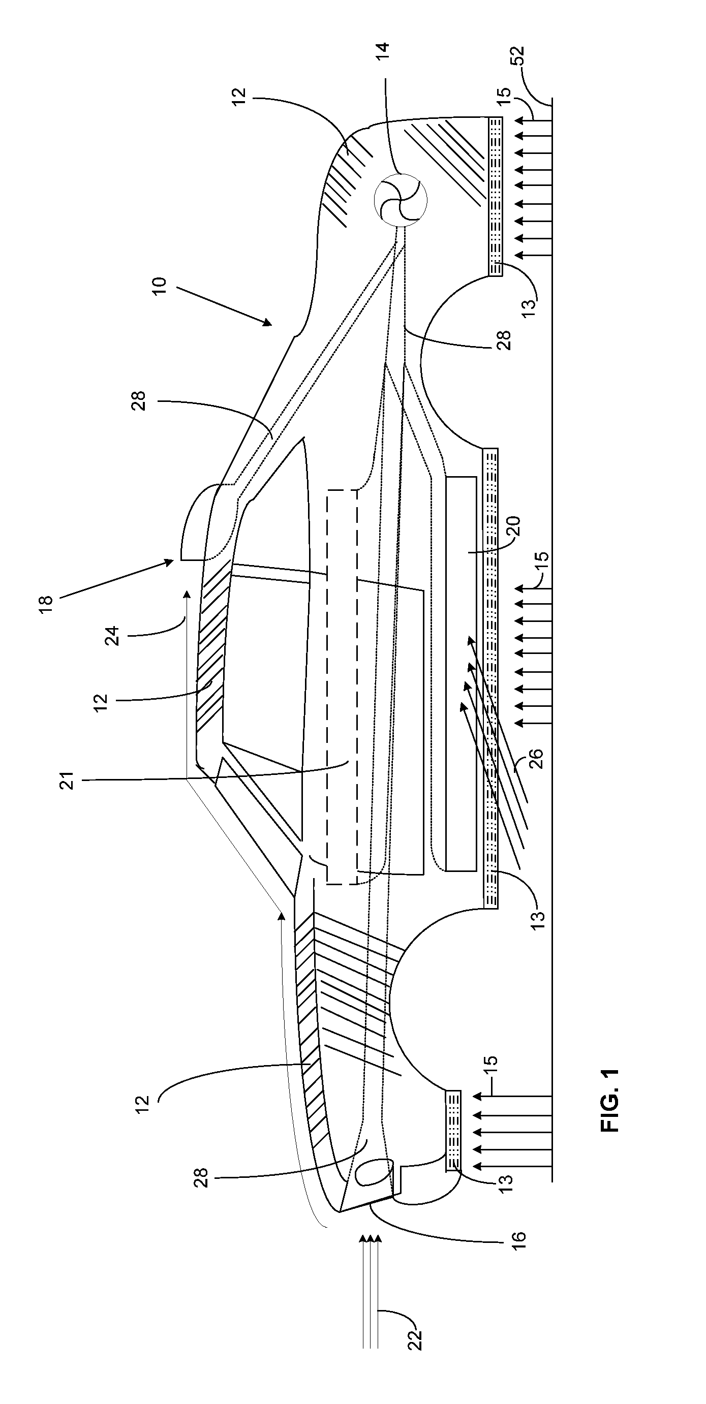
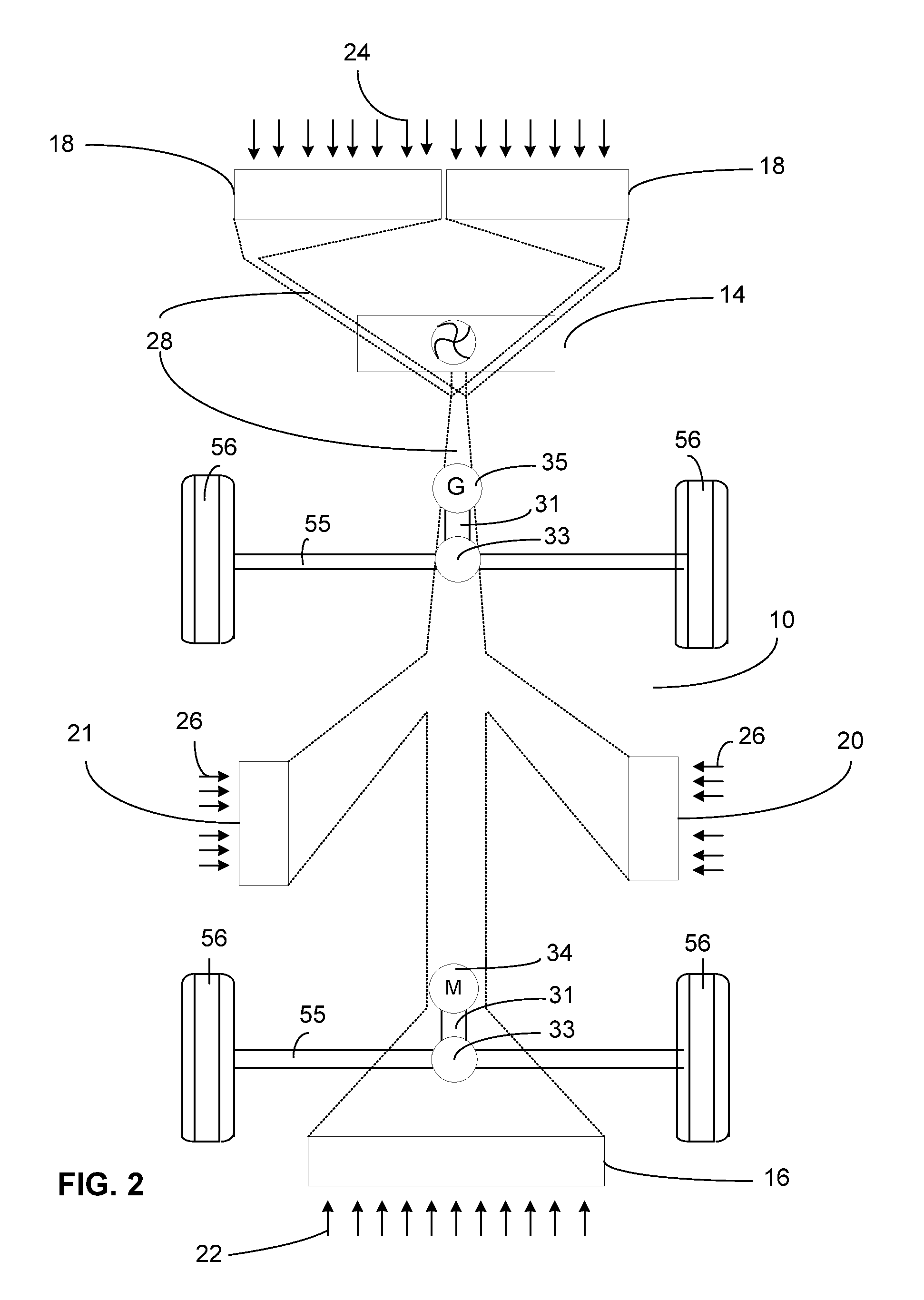
[0032]This invention relates generally to electric vehicles operated by at least one electric motor connected to a drive axel to propel said electric vehicle and rechargeable batteries to provide stored electrical energy to said electric motor; in which the electric motor is powered and the batteries are recharged by multiple power sources: solar, thermal, wind, at least one electrical generator. Solar and / or thermal power source converts solar and / or thermal energy to electricity using a plurality of solar and / or thermal panels such as one or a combination of two or more of the followings: photovoltaic (PV) panels, concentrated PV panels, thermophotovoltaic (TPV) panels, concentrated TPV panels, dye solar panels, concentrated dye solar panels, thin-film solar panels, concentrated thin-film solar panels, three-layer PV panels, concentrated three-layer PV panels, luminescent PV panels, polymer PV panels, concentrated polymer PV panels, thermoelectric generators panels, concentrated thermoelectric generators panels, hybrid solar cell panels, concentrated hybrid solar cell panels, or alike placed on the external surface of the said vehicle such as the roof, bottom, sides of the said vehicle and any other possible surfaces of the said vehicle to collect the maximum possible solar and / or thermal energy on said vehicle and convert said solar and / or thermal energy to electrical power at all times and whether the said vehicle in use or not in use for providing electrical power to said electric motor and to continuously recharge said batteries. Wind power source utilizes at least one on-board wind turbine or alike operated by an accelerated wind streams collected from front, top, right side, and left-side winds surrounding the said vehicle. Electric power generated by at least one electric generator operated by the rotation of the vehicle axels. In emergency and unpredicted conditions, the operator of said vehicle can recharge the batteries from using a power supply unit.

Problems solved by technology

A permanent connection of the electric motor to electrical power supply lines is impossible due to the mobility of the vehicles, that is, vehicles are not fixed at one location.
In previously constructed electric vehicles, batteries are typically heavy and are required in large numbers to provide an adequate driving range between recharging periods.
Therefore, such batteries still utilize electricity generated by conventional means such as fossil fuel, coal, hydro, nuclear, etc. with dire consequences to the environment and destructive impacts to humans and animals alike.
Such action ignores most of the useful wind streams surrounding the vehicle, especially the very important right side and left side wind streams, and increases drag forces on the vehicle, hence, reducing the effective electric power generated from the wind turbine's generator.
Additionally the designs are not practical or even not safe for domestic use.
Other types of electric vehicles use solar panels to generate electricity to recharge the batteries and often-such designs are not successful for regular vehicles with many passengers driving on a typical highway due to the limited area and the low efficiency of the solar panels, hence, the limited electric power they generate.
Most of the previously proposed electric vehicles have limitations in driving range, driving speed, number of passengers, and / or safety.
In addition, some electric vehicles depend directly or indirectly on fossil fuel, coal, hydro, nuclear, etc. with dire consequences to the environment.
This, in turn, will cause the same dire impacts on the environment produced by a regular fossil fuel vehicle or alike.
This design is not only dangerous but deemed useless due to the huge drag forces it generates.
Due to the limited area of the solar panels used on the vehicle and their low efficiency, electric vehicles powered exclusively by solar panels may have many limitations, especially in speed, efficiency, weight, and number of passengers.
The reliability of this vehicle is in question, especially, the design does not include any batteries to store power and derive the electrical motor during poor weather conditions when the solar energy is not adequately available.
Hence, such method is impractical, very expensive and may require repaving all the roads and the highways around the world to generate a very small portion of the energy that a vehicle may require.
While all the previous devices fulfill their respective, particular objectives and requirements, the aforementioned patents do not disclose a new reliable, self-standing, solar / thermal / wind / electrically powered electric vehicle where all or most wind forces are harnessed and converted to electricity, all or most solar energy is collected and converted to electricity, all or most radiated heat is collected and converted to electricity, and a lot of electric energy is internally harnessed by at least one electric generator.

Method used


Image

  • Green electric vehicle utilizing multiple sources of energy
  • Green electric vehicle utilizing multiple sources of energy
  • Green electric vehicle utilizing multiple sources of energy

Examples


Embodiment Construction

[0041]The detailed description set forth below is intended as description of the presently preferred embodiments of the invention, and is not intended to represent the only form in which the present invention may be constructed or utilized. The description sets forth the functions and sequences of steps for constructing and operating the invention. It is to be understood, however, that the same or equivalent functions and sequences may be accomplished by different embodiments and that they are intended to be encompassed within the scope of the invention.

[0042]With reference now to the drawings, the preferred embodiments will now be described in detail. The invention comprises in general a vehicle powered by electricity shown schematically in the drawings as vehicle 10, which as illustrated comprises four wheels 56 and either two rotating axels 55 as seen in FIGS. 2 and 4, in which case each axle 55 connects an opposing pair of wheels 56, or three axels 55 with one connecting a pair ...


PUM


Abstract

An electrically powered, engineless, self-standing, green electric vehicle comprising at least one electric motor connected to a drive axel and a plurality of rechargeable batteries to provide stored electrical energy to said motor. The said motor is propelled and the said batteries are recharged by multiple sources of energy. The vehicle may include a wind collection and acceleration system used to drive at least one wind turbine or alike to generate electricity. It may also include solar and thermal receptors means to generate electricity from solar and thermal sources. In addition, the vehicle may include at least one electric generator means connected to another axel where the rotation of the axel with transmission gearing means increase the rotational speed of the generator means to produce electricity. The vehicle may also include management control means to regulate and combine all electrical power sources and selectively direct electrical power to the said electric motor for power or the said batteries for recharge. The vehicle is capable of running without driving distance limitations under all weather conditions, day or night, without the use of fossil fuels such as diesel, gasoline, liquid gases; and without the use of alcohol or ethanol, or any other liquid gases or fuels, and without introducing toxic emissions and harmful gases to the environment.

Description

CROSS REFERENCE TO RELATED APPLICATION[0001]Not ApplicableFEDERALLY SPONSORED RESEARCH[0002]Not ApplicableSEQUENCE LISTING OR PROGRAM[0003]Not ApplicableBACKGROUND OF THE INVENTION[0004]1. Field of the Invention[0005]The present invention relates to vehicles that do not use internal combustion engines and therefore do not require diesel, gasoline, alcohol, ethanol, natural gas, or other liquid gases or fuels. In particular, the present invention relates generally to electric vehicles operated by at least one electric motor connected to a drive axel to propel said electric vehicle and rechargeable batteries to provide stored electrical energy to said electric motor; in which the electric motor is powered and the batteries are recharged by multiple power sources including solar, thermal, wind, and electrical.[0006]2. Description of the Prior Art[0007]Due to the continuous depletion of world supply of fossil fuel and the continuous increase in both fuel cost and horrible pollution to t...

Claims


Application Information

Patent Timeline
Patent Type & Authority Applications(United States)
IPC IPC(8): H02J7/35F03D9/02H02K53/00
CPCB60K16/00B60K2016/003B60K2016/006F03D9/00Y02T10/7083Y02T10/90B60L8/003B60L8/006Y02E10/72F05B2240/941Y02E10/74Y02E10/728F03D9/32F03D9/25F03D9/11F03D15/10F03D3/02F03D3/0427F03D9/007H02S10/12Y02E10/50Y02T10/7072
Inventor HASSAN, M. HASSAN
Owner HASSAN M HASSAN
Learn More