
Crowd Gate Control System and Method

a crowd gate and control system technology, applied in the field of crowd gate control, can solve the problems of increasing the size and complexity of dairy milking operations, system and method support for dairy milking operations, and proving inadequate in various respects, so as to reduce the amount of human intervention, increase efficiency, and reduce milking times

Active Publication Date: 2011-12-22
TECH HLDG
View PDF15 Cites 19 Cited by
  • Summary
  • Abstract
  • Description
  • Claims
  • Application Information

AI Technical Summary

Benefits of technology

[0004]In accordance with the teachings of the present disclosure, disadvantages and problems associated with previous systems and methods supporting dairy milking operations can be reduced or eliminated by providing a crowd gate control system and method.
[0007]Various embodiments of the present disclosure may provide various technical advantages. One advantage is the ability to provide a crowd gate control system and method. Another advantage is to automatically engage a crowd gate in a series of movements that encourage dairy livestock to move towards an entrance to a milking parlor. The crowd gate may move without startling, agitating, and / or harming the dairy livestock. Accordingly, dairy livestock may be trained over time to move forward towards the entrance to the milking parlor on their own. Another technical advantage may be to automatically determine when and / or how long to move the crowd gate. For example, movement of the crowd gate may be based on the number of dairy livestock remaining in the holding pen. Yet another advantage may be the ability to automatically reset the crowd gate when the holding pen is empty. The ability to automatically encourage dairy livestock to enter a milking parlor may increase efficiency by reducing milking times and reducing the amount of human intervention required to encourage dairy livestock to enter the milking parlor.

Problems solved by technology

Over time, the size and complexity of dairy milking operations has increased.
Systems and methods supporting dairy milking operations, however, have proven inadequate in various respects.

Method used


Image

  • Crowd Gate Control System and Method
  • Crowd Gate Control System and Method
  • Crowd Gate Control System and Method

Examples


Embodiment Construction

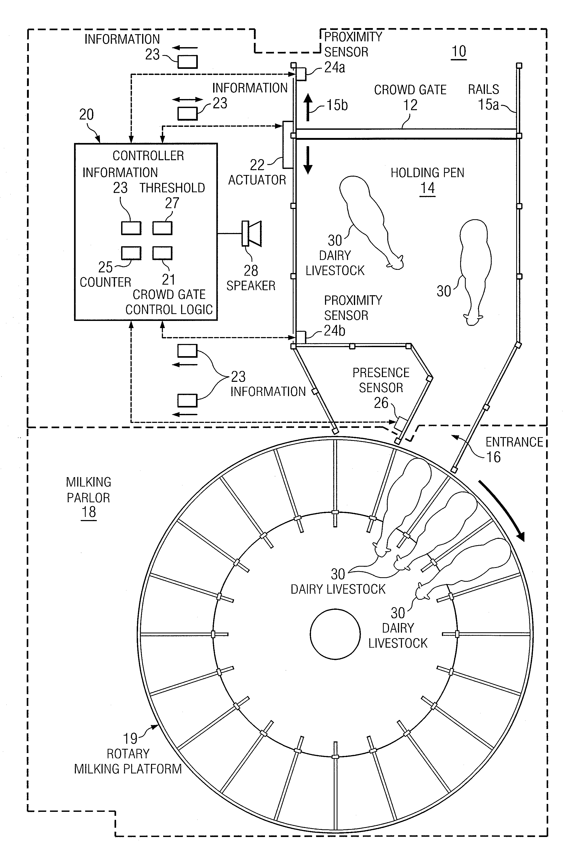
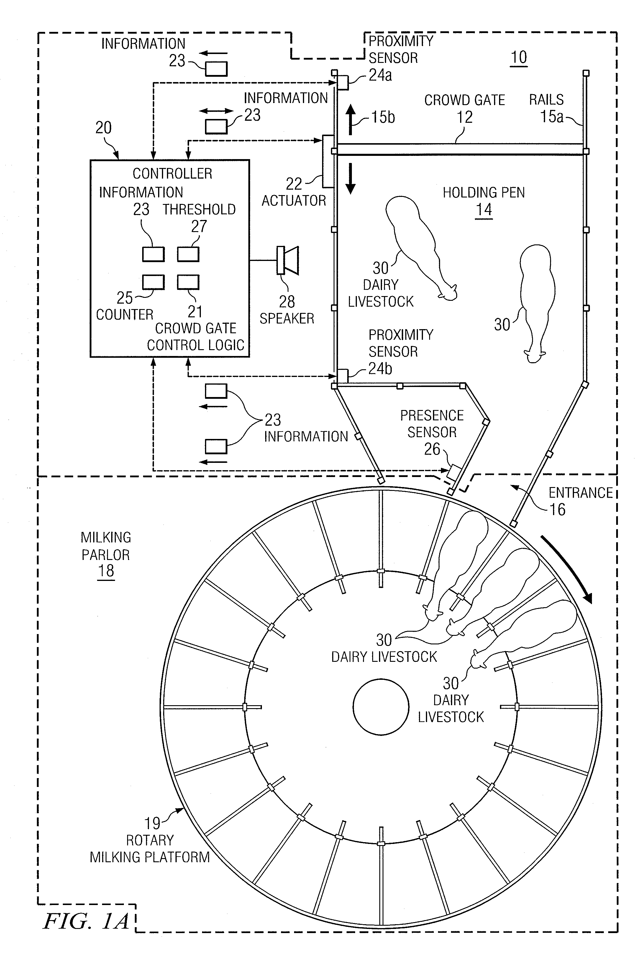
[0012]FIG. 1A is a top view diagram illustrating an example embodiment of a crowd gate control system 10. System 10 includes a crowd gate 12, a holding pen 14, rails 15, and an entrance 16. Also shown is a milking parlor 18 that includes a rotary milking platform 19. In general, a group of dairy livestock 30, such as dairy cows, enter the holding pen 14 and wait for their turn to be milked, each in turn passing through entrance 16 to rotary milking platform 19. Crowd gate 12 is generally operable to move along rails 15 towards and away from entrance 16, thereby respectively decreasing and increasing the effective area of holding pen 14. System 10 also includes a controller 20, an actuator 22, proximity sensors 24a and 24b, a presence sensor 26, and a speaker 28. Controller 20 generally controls the operation of elements within system 10. For example, controller 20 may control the movement of crowd gate 12 in several modes of operation by sending and / or receiving information 23 to an...


PUM


Abstract

A crowd gate control system includes a holding pen for dairy livestock, a crowd gate, and a controller. The holding pen is adjacent to an entrance to a milking parlor. The crowd gate is operable to form a side of the holding pen and move in relation to the entrance to the milking parlor along an axis substantially parallel to two other sides of the holding pen. The controller is operable to store a triggering threshold associated with a counter related to the milking parlor, determine whether the counter has reached the triggering threshold, and initiate a first mode of operation of the crowd gate in response to determining that the counter has reached the triggering threshold.

Description

CROSS-REFERENCE TO RELATED APPLICATION[0001]This application claims the benefit of priority under 35 U.S.C. §119(e) of U.S. Provisional Application 61 / 356,998 filed Jun. 21, 2010.TECHNICAL FIELD OF THE DISCLOSURE[0002]This disclosure relates generally to crowd gates, and, more particularly, to a system and method for crowd gate control.BACKGROUND OF THE DISCLOSURE[0003]Over time, the size and complexity of dairy milking operations has increased. Accordingly, the need for efficient and scalable systems and methods that support dairy milking operations also has increased. Systems and methods supporting dairy milking operations, however, have proven inadequate in various respects.SUMMARY OF THE DISCLOSURE[0004]In accordance with the teachings of the present disclosure, disadvantages and problems associated with previous systems and methods supporting dairy milking operations can be reduced or eliminated by providing a crowd gate control system and method.[0005]According to an exemplary...

Claims


Application Information

Patent Timeline
IPC IPC(8): A01K1/12A01J5/003
CPCA01K1/0029A01K1/126A01K1/12
Inventor SIDDELL, JAMES D.
Owner TECH HLDG
Learn More