
Blood drawing device with flash detection

a blood drawing and flash detection technology, applied in the field of bodily fluid apparatus drawing, can solve the problems of undermining the integrity of the specimen, patient harm additionally, and flash detection has been less than satisfactory in many such collection assemblies

Inactive Publication Date: 2011-12-15
CLEARVIEW PATIENT SAFETY TECH
View PDF0 Cites 43 Cited by
  • Summary
  • Abstract
  • Description
  • Claims
  • Application Information

AI Technical Summary

Benefits of technology

"The patent describes a guide tube assembly for drawing fluid from a lumen. It includes a guide tube with an open end and a well, a flexible sleeve with an interior space in fluid communication with the well, and passages extending through the guide tube in fluid communication with the flexible sleeve interior space. The assembly also includes a venting member connected to the guide tube or incorporated into the flexible sleeve, which is in fluid communication with the passages and disposed between the flexible sleeve interior space and an ambient. The technical effect of this invention is to provide a reliable and efficient tool for drawing fluid from a lumen."

Problems solved by technology

If the needle tip is not in communication with the interior of the blood vessel during the procedure, the procedure is likely to be unsuccessful, causing error, undermining the integrity of the specimen, and the patient may be harmed additionally by the penetration of delicate underlying structures.
The observation of blood in the needle body is known as “flash.” Flash detection has been less than satisfactory for many such collection assemblies.
This delay can impede the determination of the precise moment at which the needle tip enters the blood vessel, which may cause the healthcare worker inserting the needle to miss or perforate the vessel and penetrate into delicate surrounding structures.
In other instances, while flash occurs, the visual indication of flash is not easily detected because the amount of flash is small or obscured due to the positioning of the collection assembly.
There are also many needles that are currently used that do not provide for flash detection.

Method used


Image

  • Blood drawing device with flash detection
  • Blood drawing device with flash detection
  • Blood drawing device with flash detection

Examples


Embodiment Construction

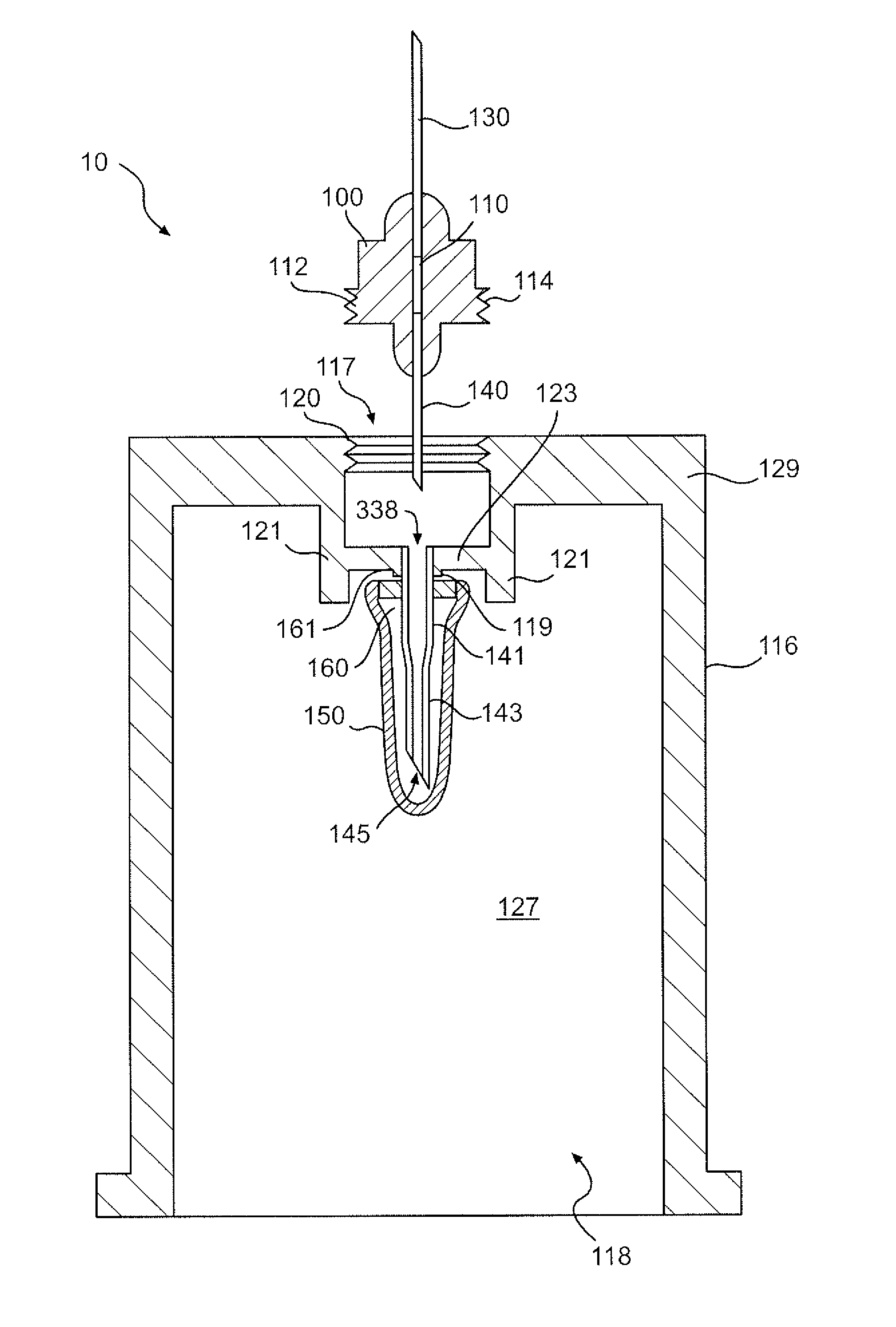
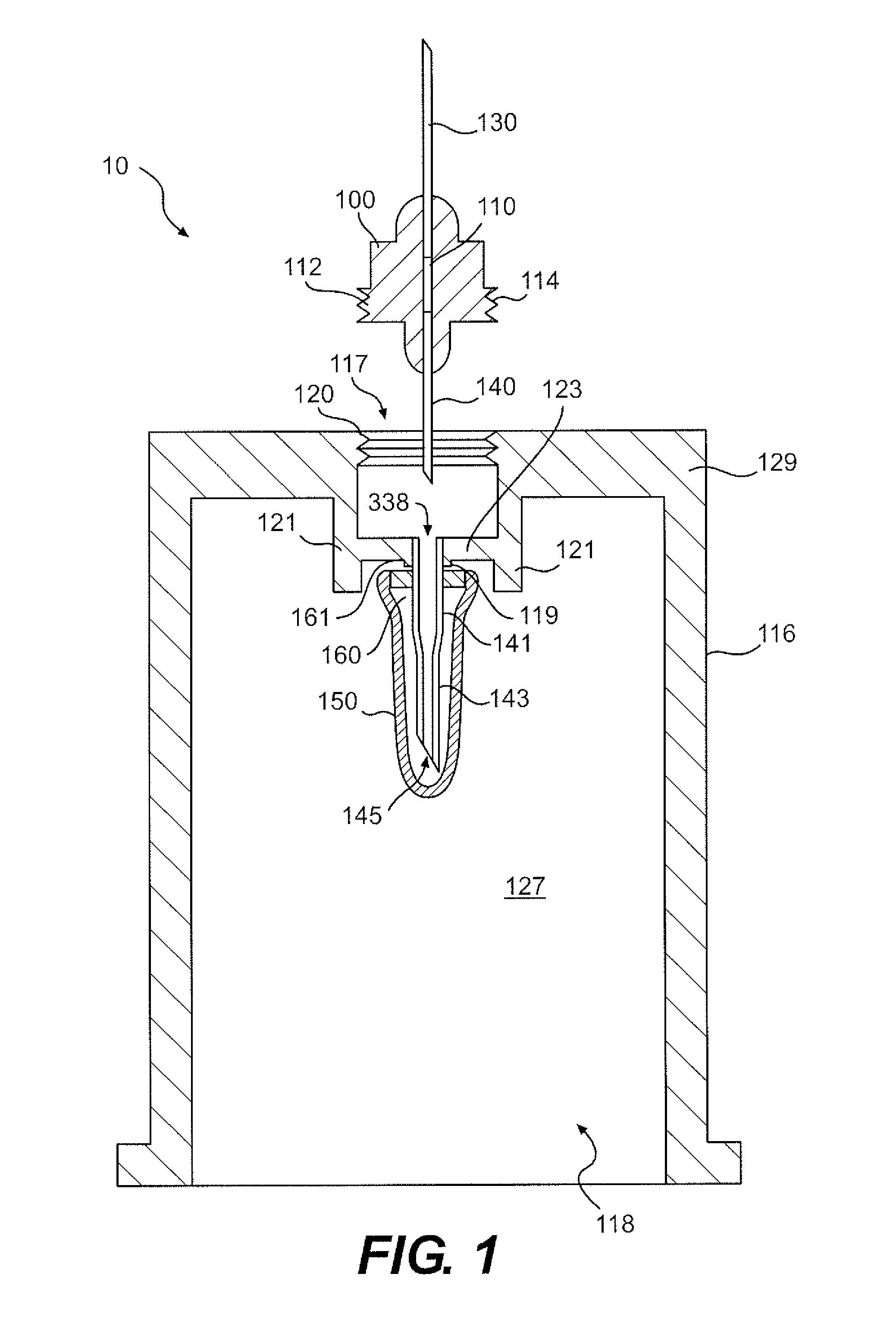
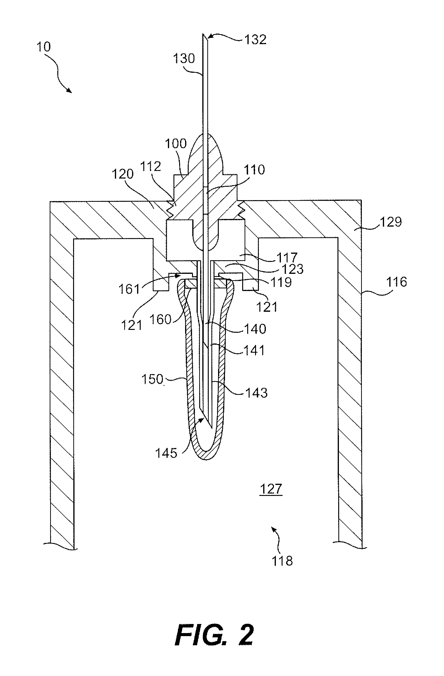
[0033]Reference will now be made in detail to a first embodiment of the present invention, an example of which is illustrated in the accompanying drawings. With reference to FIGS. 1 and 2, a guide tube 116 is shown. The guide tube 116 is provided for connection to a central body 100 which may include one or more constituent elements, such as a threaded connector 112 with interlocking threads 114 or other connection means, for connecting the central body to the guide tube. The threaded connector 112 may be integrally formed with, or connected to the central body using adhesive, male-female interfaces, threaded interfaces, or any other connection means. It is appreciated that the guide tube 116 may be connected to the central body 100 by any connection means, including without limitation the threaded interfaces shown, male-female interfaces, pressure-fit connectors, slot and key connectors, snap-on connectors, and the like. The type of connection between the guide tube 116 and the cen...


PUM


Abstract

A device for drawing fluid from a lumen, and particularly blood from a blood vessel, is disclosed. The device may provide indication of the entry of an intravenous cannula into the lumen. The device may include a guide tube for receiving a blood sample container and which may be connected to a needle for drawing blood from a lumen. A rear cannula may extend into the guide tube from the well. A flexible sleeve may be mounted on a barb connected to the guide tube. The flexible sleeve may extend into the guide tube from the well and surround at least a tip portion of the rear cannula. A venting member may be provided between the interior of the sleeve and the ambient. The venting member may permit air to vent from the flexible sleeve without venting blood, so that flash can be detected. In some, but not all, embodiments, one or more passages may be provided in guide tube to facilitate the venting of air from the flexible sleeve.

Description

CROSS-REFERENCE TO RELATED APPLICATIONS[0001]The present application relates to, is a continuation in part of, and claims the benefit of earlier filed U.S. patent application Ser. No. 11 / 889,536 which was filed Aug. 14, 2007 and entitled “Blood Drawing Device with Flash Detection,” which relates to, is a continuation in part of, and claims the benefit of earlier filed U.S. patent application Ser. No. 10 / 836,232 which was filed May 3, 2004 and entitled “Blood Drawing Device with Flash Detection,” and which prior applications are both incorporated herein by reference.FIELD OF THE INVENTION[0002]The present invention relates to an apparatus for drawing bodily fluids, and particularly blood, from an animal.BACKGROUND OF THE INVENTION[0003]Intravenous blood collection assemblies have long been used to draw bodily fluids, such as blood, from patients. With respect to drawing blood in particular, the vessel or lumen from which the blood is drawn is often rather small and or not visible. If...

Claims


Application Information

Patent Timeline
Patent Type & Authority Applications(United States)
IPC IPC(8): A61B5/153A61B5/15A61B5/155A61M25/00A61M25/06
CPCA61B5/1427A61B5/1438A61M25/0693A61B5/154A61B5/155A61B5/1444A61B5/15003A61B5/150213A61B5/150389A61B5/150473A61B5/150572A61B5/150732A61B5/15074A61B5/1545
Inventor BROWN, LEROY R.FISCHEL, LLOYD S.
Owner CLEARVIEW PATIENT SAFETY TECH
Learn More