
Temperature Measuring Apparatus

Active Publication Date: 2011-12-15
AVITA
View PDF4 Cites 1 Cited by
  • Summary
  • Abstract
  • Description
  • Claims
  • Application Information

AI Technical Summary

Benefits of technology

[0009]It will be appreciated that the present invention provides an infrared temperature measuring apparatus which can be operated to measure temperature without utilizing any measuring button so as to maintain an operation stability of the apparatus, reduce the error of the temperature measuring result and render the temperature measuring operation being more convenient.
[0024]Accordingly, the trigger device of the temperature measuring apparatus according to a preferred embodiment of the present invention is arranged corresponding with the probe thereof and the trigger device connects the casing with the probe. Therefore, when the probe moves toward the casing, the trigger device is activated to trigger the infrared sensor assembly to proceed sensing. Hence, the user can operate temperature sensing measurement simply by means of the triggering of the trigger device, resulting that the stability of the temperature measuring operation can be maintained without the need and operation of any measuring button.

Problems solved by technology

However, due to the limitation of the contact area and the portion to be measured, the temperature measurement operation is relatively slow and inaccurate.
Especially during the body temperature measurement of a baby, it is difficult to conduct a long time measuring.
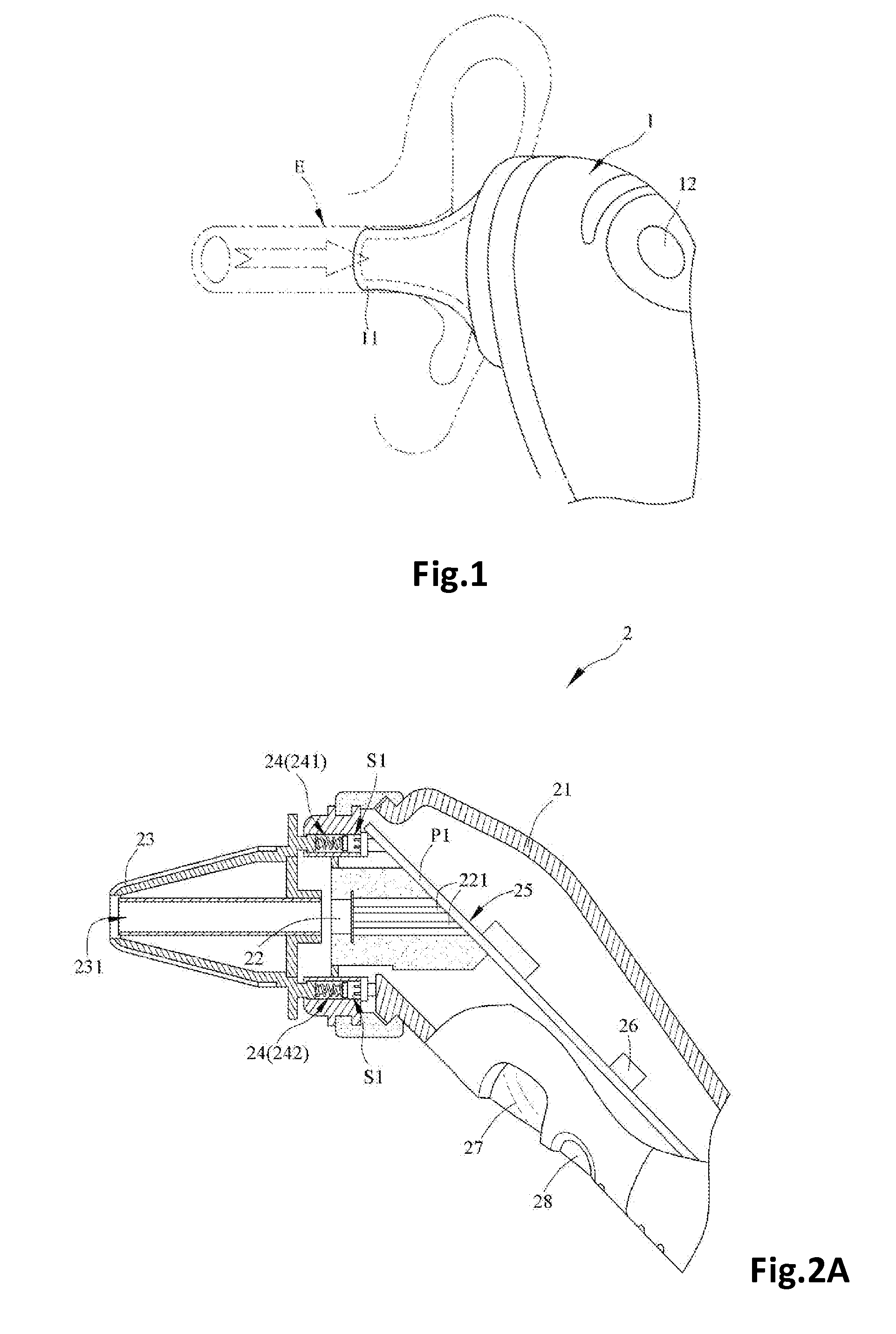
However, when the above mentioned ear-temperature measuring gun 1 is used to measure temperature, since the measuring button 12 for triggering the measuring is disposed on the casing, it is difficult for the user to control when should be the right time to press down the measuring button 12.
In addition, it is difficult for the user to operate and press down the measuring button 12 with his or her finger while aiming the ear-temperature measuring gun 1 at the auditory canal E, resulting in indirectly reducing the stability of the measuring procedure and adversely affecting the accuracy of the temperature measurement.

Method used


Image

  • Temperature Measuring Apparatus
  • Temperature Measuring Apparatus
  • Temperature Measuring Apparatus

Examples


Embodiment Construction

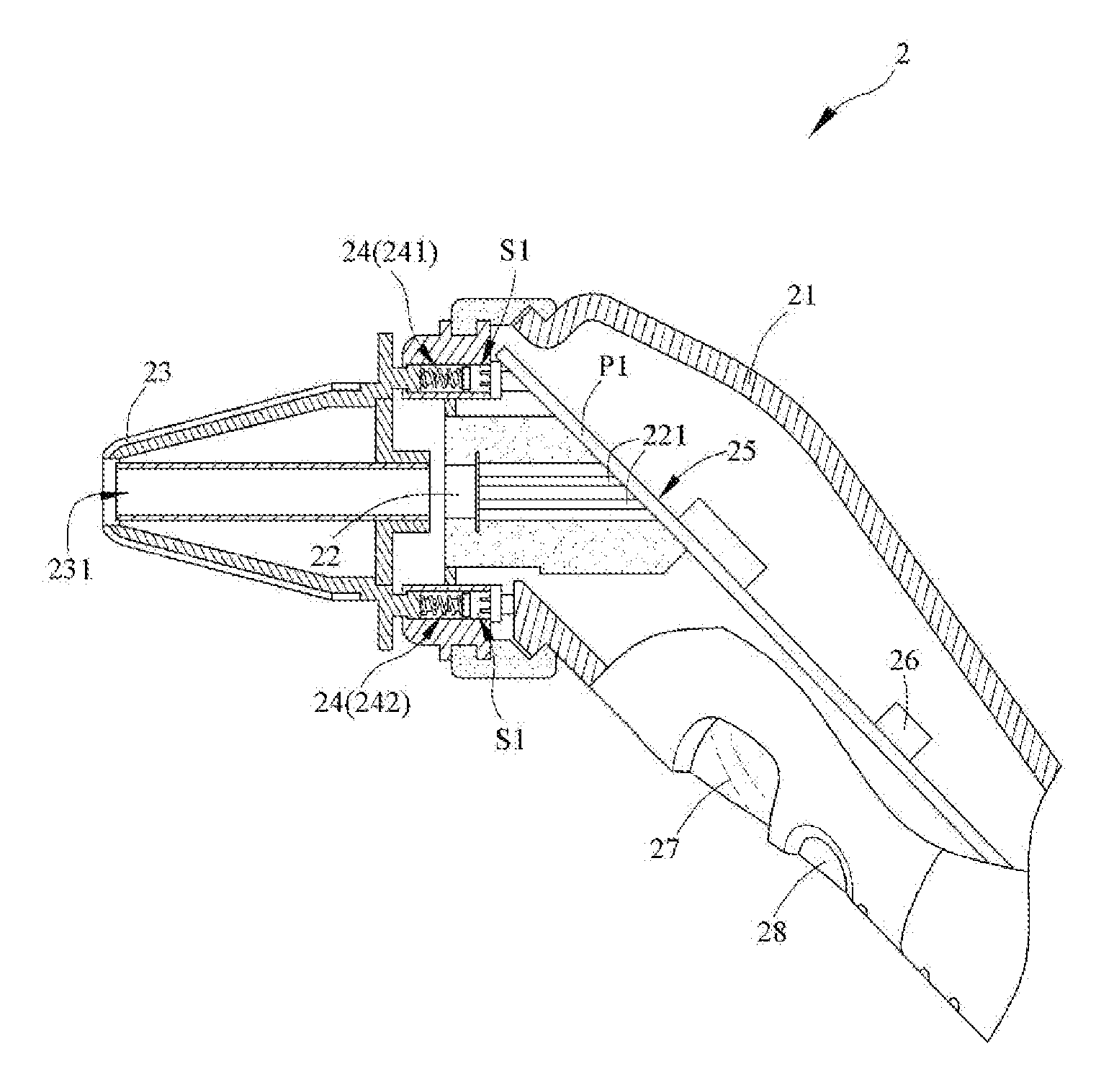
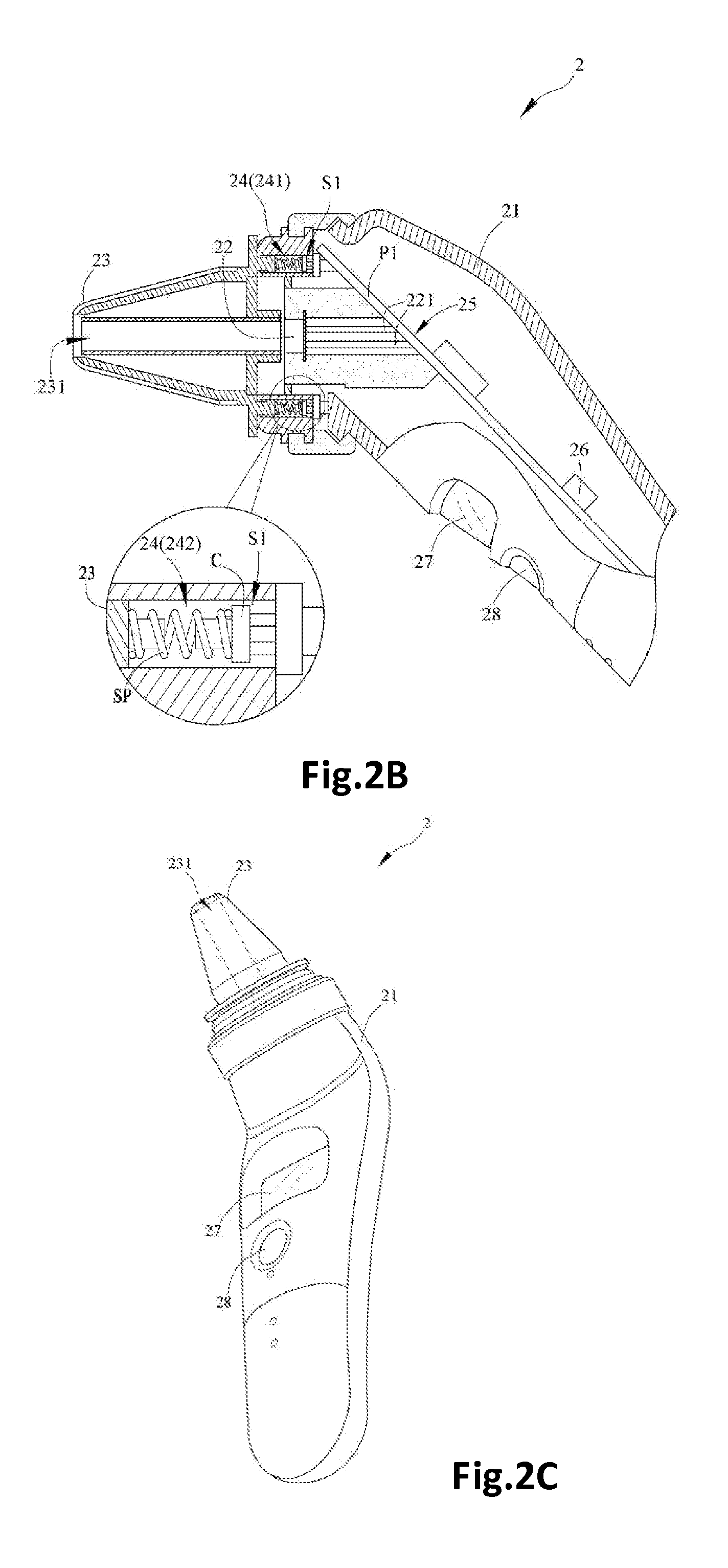
[0033]Referring to FIGS. 2A, 2B and 2C, FIG. 2A and FIG. 2B are sectional views of a temperature measuring apparatus according to a first preferred embodiment of the present invention, and FIG. 2C is a perspective view of the temperature measuring apparatus. FIG. 2A is a sectional view illustrates the temperature measuring apparatus during an un-measuring mode, while FIG. 2B illustrates the temperature measuring apparatus with the probe being pushed to a measuring mode.

[0034]The temperature measuring apparatus 2 comprises a casing 21, an infrared sensor assembly 22, a probe 23 and a trigger device 24. The temperature measuring apparatus 2 is an infrared temperature measuring apparatus, which could be structurally designed for measuring temperatures of different portions with different structures and names, such as, but not limited to, ear-temperature measuring gun, forehead-temperature measuring gun or forehead and ear temperature measuring gun.

[0035]The infrared sensor assembly 22 ...


PUM


Abstract

A temperature measuring apparatus comprises a casing, an infrared sensor assembly, a probe, and a trigger device. The infrared sensor assembly is disposed in the casing. The trigger device is connected between the casing and the probe in such manner that when the probe moves toward the casing, the trigger device is activated by the probe to trigger the infrared sensor assembly to proceed sensing. The temperature measuring apparatus could be operated to measure without pressing any measuring button, so that the temperature measuring apparatus could have a stable operation in the measuring process. Hence, the error of the temperature measuring is reduced and the operation is more convenient.

Description

BACKGROUND OF THE PRESENT INVENTION[0001]1. Field of Invention[0002]The present invention relates to a temperature measuring apparatus, and more particularly to an infrared temperature measuring apparatus.[0003]2. Description of Related Arts[0004]The conventional contact thermometer, such as the mercury-in-glass thermometer or the electrical resistance thermometer, should generally be contacted to the subject to be measured for a longer time for temperature measurement. However, due to the limitation of the contact area and the portion to be measured, the temperature measurement operation is relatively slow and inaccurate. Especially during the body temperature measurement of a baby, it is difficult to conduct a long time measuring. Such problems could be resolved if the infrared sensor would be adopted in the temperature measuring.[0005]The subjects with different temperatures will respectively radiate infrared rays with different frequencies, so a device for receiving infrared ray...

Claims


Application Information

Patent Timeline
IPC IPC(8): G01J5/00
CPCG01J5/0011G01J5/049G01J5/027G01J5/0205
Inventor YANG, TA CHIEH
Owner AVITA
Learn More