
Systems and methods for dipole enhanced inductive power transfer

a dipole enhanced inductive power and power transfer technology, applied in the direction of inductances, continuous variable inductances/transformers, cores/yokes, etc., can solve the problem of q being much greater than 100, unable or undesirable to be placed, and other limitations of the related art will become apparen

Active Publication Date: 2011-12-15
THE UNIV OF BRITISH COLUMBIA
View PDF1 Cites 72 Cited by
  • Summary
  • Abstract
  • Description
  • Claims
  • Application Information

AI Technical Summary

Problems solved by technology

Normally, such coupling is achieved by placing the coils in extreme proximity to one another, but in some cases such placement may be impossible or undesirable.
It is impractical for Q to be much greater than 100, and even in that case it is necessary to employ RF frequencies, which is of potential concern, due to the lack of long-term epidemiological studies of possible medical side effects associated with time-varying fields.
Other limitations of the related art will become apparent to those of skill in the art upon a reading of the specification and a study of the drawings.

Method used


Image

  • Systems and methods for dipole enhanced inductive power transfer
  • Systems and methods for dipole enhanced inductive power transfer
  • Systems and methods for dipole enhanced inductive power transfer

Examples


Embodiment Construction

[0022]Throughout the following description specific details are set forth in order to provide a more thorough understanding to persons skilled in the art. However, well known elements may not have been shown or described in detail to avoid unnecessarily obscuring the disclosure. Accordingly, the description and drawings are to be regarded in an illustrative, rather than a restrictive, sense. Before the embodiments of the invention are explained in detail, it is to be understood that the invention is not limited in its application to the details of construction and the arrangements of the operative components set forth in the following description or illustrated in the drawings. The invention is capable of other embodiments and of being practiced or being carried out in various ways. Also, it is understood that the phraseology and terminology used herein are for the purpose of description and should not be regarded as limiting. The use herein of “including” and “comprising”, and vari...


PUM

PropertyMeasurementUnit
frequencyaaaaaaaaaa
resonant frequenciesaaaaaaaaaa

Abstract

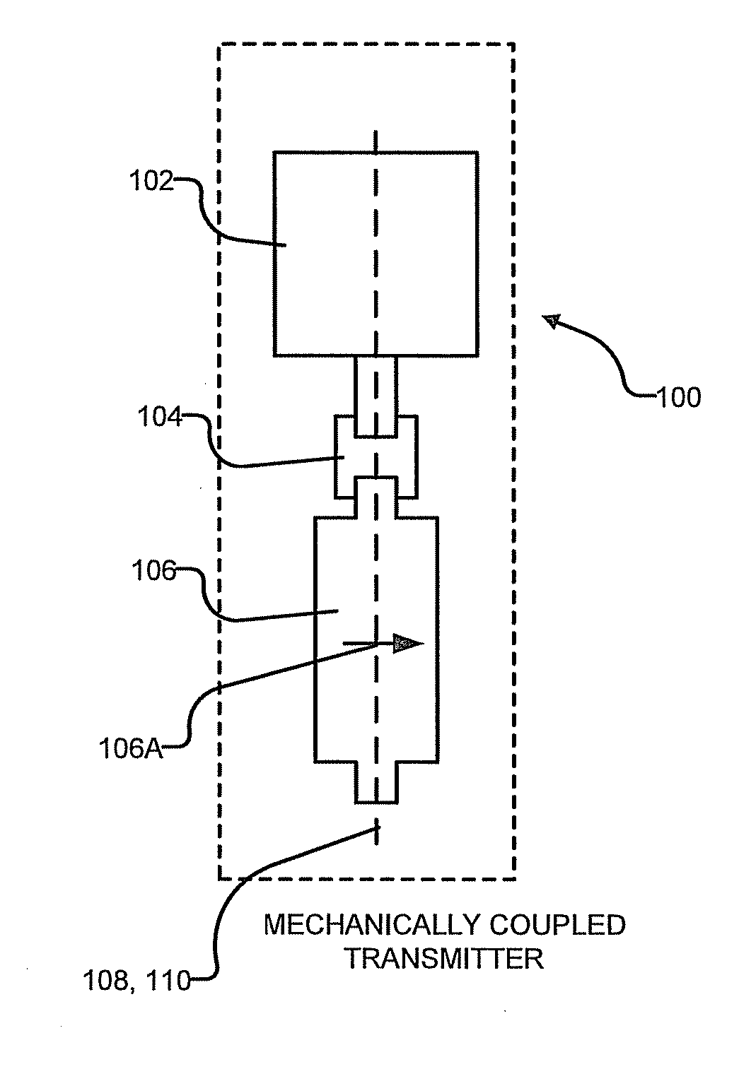
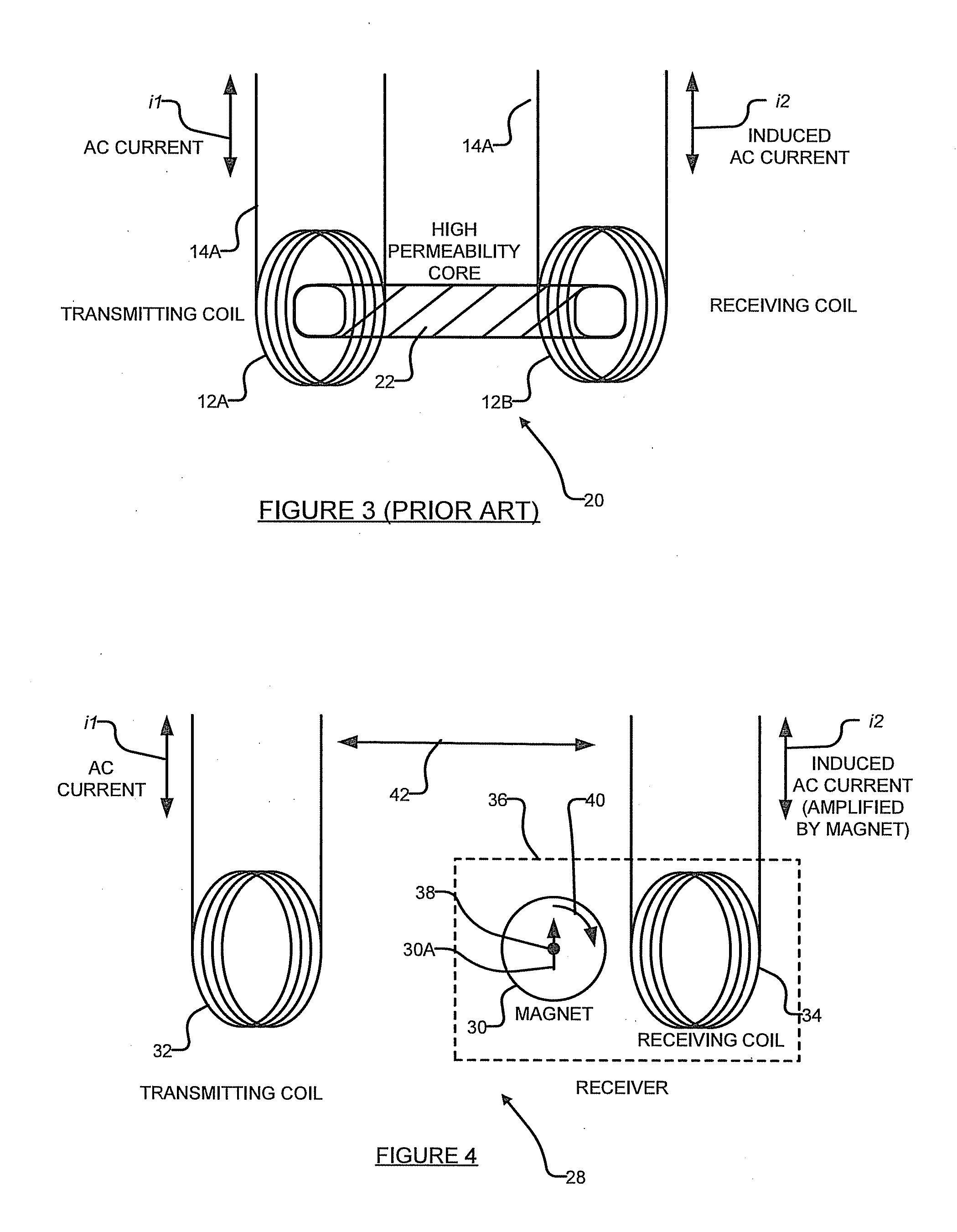
An inductive power transfer apparatus is disclosed. A transmitter generates a first time varying magnetic field. A receiver is separated from the transmitter by a gap, but is located with the first time varying magnetic field. The receiver comprises: a conductor; and a receiver magnet located in the first time varying magnetic field and supported for movement in response to the first time varying magnetic field. The conductor and receiver are positioned relative to one another such that movement of the receiver magnet creates a second time-varying magnetic field in a vicinity of the conductor to thereby induce current in the conductor.

Description

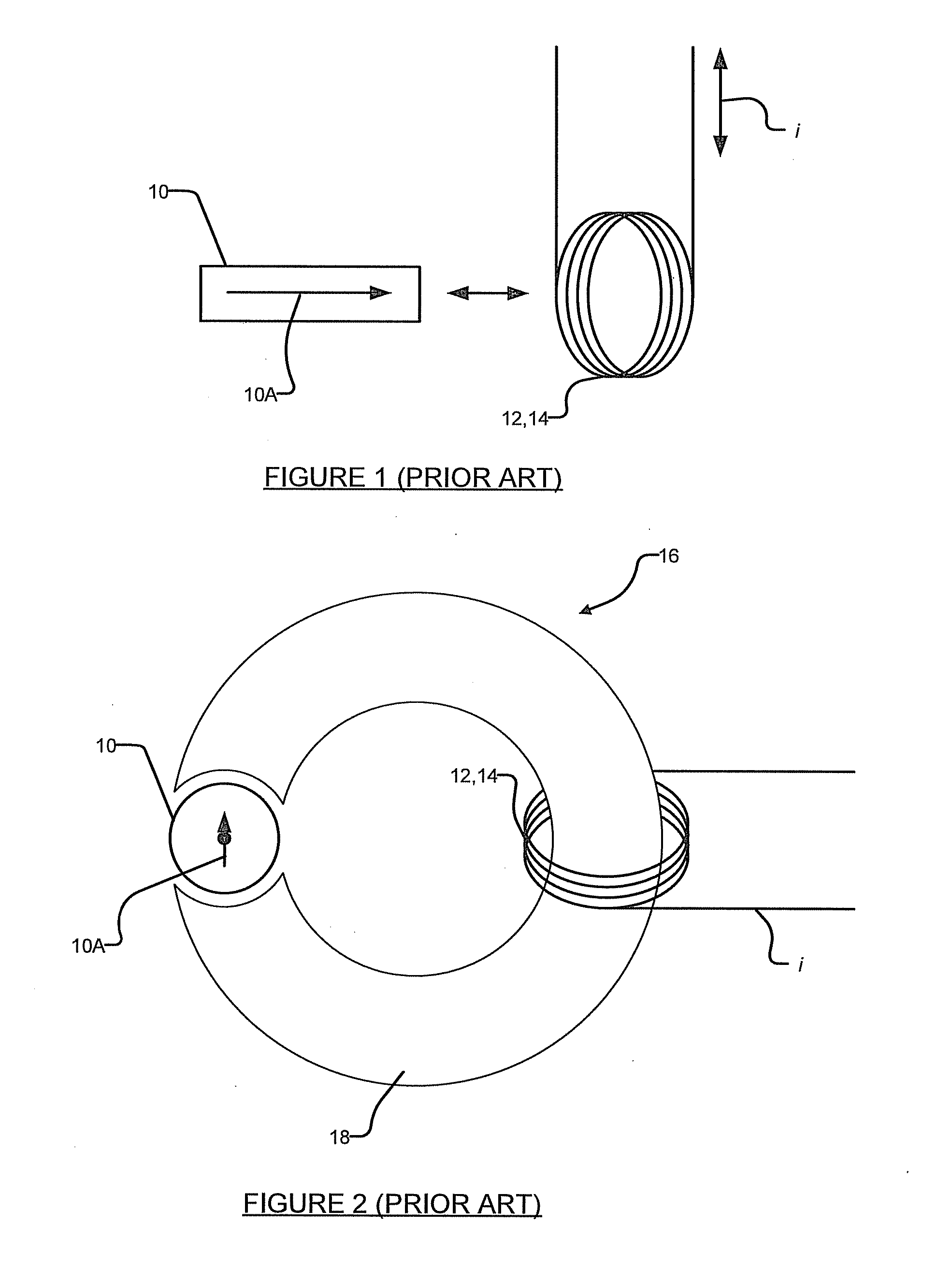
RELATED APPLICATIONS[0001]This application claims the benefit of the priority of U.S. application No. 61 / 155,886 filed on 26 Feb. 2009 which is hereby incorporated herein by reference.TECHNICAL FIELD[0002]This disclosure concerns low frequency inductive power transfer from one location to another, through the use of field enhancement derived from permanent magnets.BACKGROUND OF INVENTION[0003]It is well known that power can be wirelessly conveyed from one place to another using the Faraday effect, whereby a changing magnetic field causes an electrical current to flow in an electrically isolated secondary circuit.[0004]Such power transfer is reasonably efficient, given highly efficient coupling between the primary coil which creates the changing magnetic field and the secondary coil that is acted upon by the changing magnetic field. Normally, such coupling is achieved by placing the coils in extreme proximity to one another, but in some cases such placement may be impossible or undes...

Claims


Application Information

Patent Timeline
Patent Type & Authority Applications(United States)
IPC IPC(8): H02J17/00H01F38/14
CPCH01F21/08H01F2003/103H02J17/00H04B5/0087H02J5/005H04B5/263H02J50/12H02J50/90H02J50/10
Inventor WHITEHEAD, LORNE A.
Owner THE UNIV OF BRITISH COLUMBIA
Learn More