
Laundry machine

a washing machine and drum technology, applied in the field of washing machines, can solve the problems of increasing the size of the tub, limiting the size change etc., and achieve the effects of increasing the capacity of the washing machine, improving the rotation efficiency of the drum, and increasing the capacity

Active Publication Date: 2011-12-08
LG ELECTRONICS INC
View PDF2 Cites 8 Cited by
  • Summary
  • Abstract
  • Description
  • Claims
  • Application Information

AI Technical Summary

Benefits of technology

[0043]By changing a structure of the washing machine, a capacity of the washing machine can be increased.
[0044]Moreover, by providing a driving structure that can rotate the drum having a capacity increased thus effectively, a rotation efficiency of the drum can be improved.

Problems solved by technology

The drum type washing machine causes vibration inevitably due to rotation force of the drum and eccentricity of the laundry when the drum rotates for washing and spinning the laundry introduced to the drum, and the vibration generated thus is transmitted to an outside of the washing machine through the tub and the cabinet.
Thus, in a case of the drum type washing machine, change of an inside structure thereof is limited by the springs and the damper structures between the tub and the cabinet provided for moderating the vibration, and as the washing machine installation environment is limited, the size change of the washing machine is also limited.
However, due to above limiting condition, there is many difficulties for increasing a size of the tub for increasing the washing capacity within a related art drum type washing machine structure.

Method used


Image

  • Laundry machine
  • Laundry machine
  • Laundry machine

Examples


Embodiment Construction

[0051]Reference will now be made in detail to the specific embodiments of the present invention, examples of which are illustrated in the accompanying drawings. Wherever possible, the same reference numbers will be used throughout the drawings to refer to the same or like parts.

[0052]In describing the present invention, names of elements of the washing machine are given taking functions thereof into account. Therefore, the names should not be understood that the name defines the element technically. Moreover, the names given to the elements can be called in other names in this field of art.

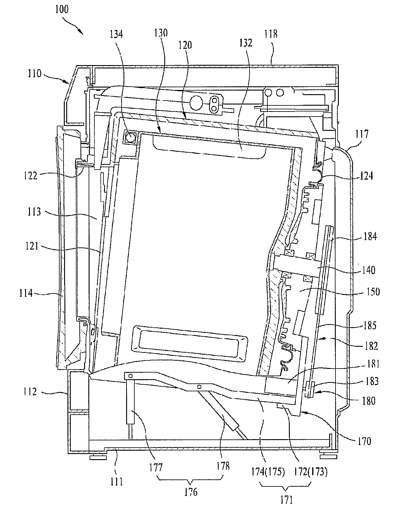
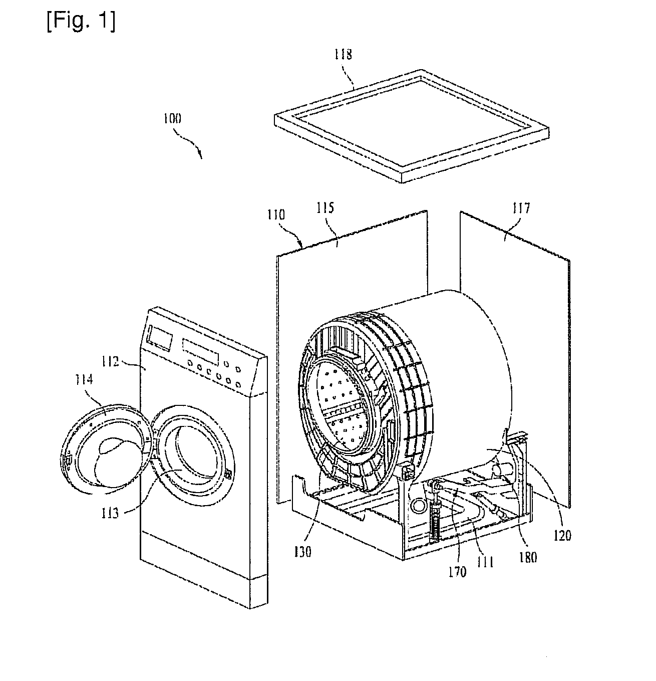
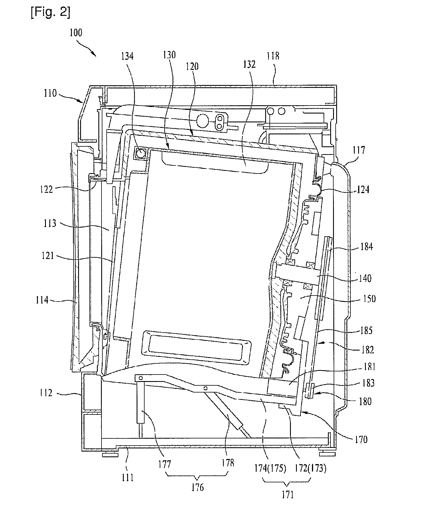
[0053]FIG. 1 illustrates a perspective view of a washing machine in accordance with a preferred embodiment of the present invention schematically, and FIG. 2 illustrates a longitudinal section of a washing machine in accordance with a preferred embodiment of the present invention.

[0054]Referring to FIGS. 1 and 2, the washing machine 100 includes a cabinet 110 which forms an exterior of the washing...


PUM


Abstract

The present invention relates to a washing machine (100) including a cabinet (110) having a base (1.11), a tub (120) fixedly secured to an inside of the cabinet (110), a drum (130) rotatable provided in the tub (120), a rotation shaft (140) passed through the tub (120) from a rear of the drum (130), a bearing housing (150) connected to the rotation shaft (140), a suspension assembly (170) for buffering and supporting a structure connected to the bearing housing (150), a driving motor (181) provided to the suspension assembly (170) and a power transmission member (182) for transmission of the rotation force from the driving motor (181) to the rotation shaft (140), thereby permitting to increase a capacity of the washing machine (100) by changing the structure or the washing machine (100) and increase the rotation efficiency of the drum (130) by providing a driving structure which rotates the drum (130) and has an increased capacity by thus effects.

Description

TECHNICAL FIELD[0001]The present invention relates to washing machines, and more specifically, to a washing machine in which a drum rotating driving structure is improved for a tub fixed type washing machine which has an increased washing capacity.BACKGROUND ART[0002]In general, the washing machine is an appliance for removing various contaminants from clothes and beddings by using softening action of detergent, friction of water flow caused by rotation of a pulsator or a drum, impact applied to the laundry, and so on. Recent full automatic washing machine carries out a series of courses, such as a washing course, a rinsing course, a spinning course without intermediate user's operation.[0003]It is recent trend that demands for drum type washing machine increases gradually, which, not only can reduce a total height compared to a pulsator type washing machine in which a washing tub rotates in an upright state, but also does not cause a problem of laundry entangling and crumpling.[000...

Claims


Application Information

Patent Timeline
Patent Type & Authority Applications(United States)
IPC IPC(8): D06F23/00
CPCD06F37/22D06F37/206D06F37/30D06F37/04
Inventor MOON, SUK YUNKWON, IG GEUNLEE, DONG IL
Owner LG ELECTRONICS INC
Learn More