
Wrist protecting glove and methods thereof

a technology for protecting gloves and wrists, applied in the field of wrist protection gloves, can solve the problems of many injuries, excruciating pain, and quick disassembly of enjoyable sensations, and achieve the effect of minimising the restriction of the range of movemen

Inactive Publication Date: 2011-12-08
MITCHELL JUSTIN M
View PDF11 Cites 2 Cited by
  • Summary
  • Abstract
  • Description
  • Claims
  • Application Information

AI Technical Summary

Benefits of technology

[0011]Embodiments of the present invention generally relate to a wrist protecting glove and methods of manufacturing the same. More specifically, embodiments of the present invention relate to a wrist protecting glove providing maximum protection with minimal restriction on range of movement, and method of manufacturing the same.

Problems solved by technology

Sports such as skateboarding, rollerblading, snowboarding, are both extremely exciting and quite dangerous.
However, if one should fall on the concrete or in the snow / ice, the enjoyable sensation may quickly depart and be replaced by excruciating pain in the event of an injury.
Similarly, many injuries occur when a skateboarder falls, and subconsciously reaches a hand down to brace the impact of the fall.
Most protective gloves in the market today suffer from the same problems.
However, with rigidity comes lack of movement, and thus, the user may be limited in his or her wrist mobility and ability to perform stunts wearing such protection.
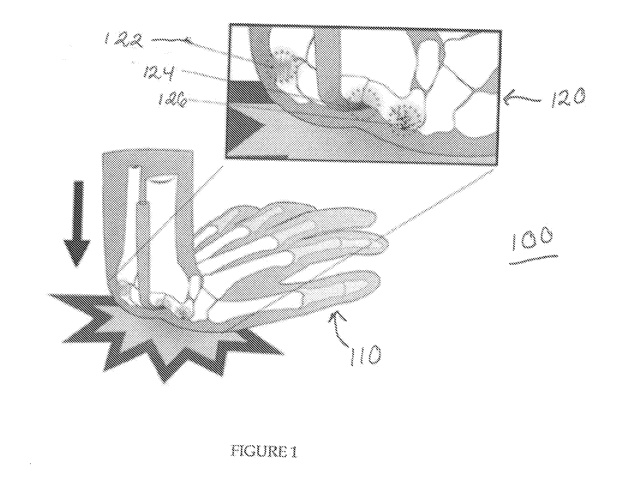
In view of the forces experienced when a user falls and puts his or her hand down, as shown in FIG. 1, such minimal protection is futile, and the user is likely to be injured.

Method used


Image

  • Wrist protecting glove and methods thereof
  • Wrist protecting glove and methods thereof
  • Wrist protecting glove and methods thereof

Examples


Embodiment Construction

[0036]Embodiments of the present invention generally relate to a wrist protecting glove and methods of manufacturing the same. More specifically, embodiments of the present invention relate to a wrist protecting glove providing maximum protection with minimal restriction on range of movement, and method of manufacturing the same.

[0037]FIG. 2 depicts a basic schematic of a palm of a wrist protecting glove in accordance with one embodiment of the present invention. The palm 200 generally comprises a top side 202 and a bottom side 204, both side by side in the Figure. The palm 200 generally comprises a pad 210 and a holding material 220 which is integrally formed with the pad 210 as described herein. In one embodiment, the pad 210, when viewed through the cross-section A-A, comprises waffle-patterned synthetic material 212, integrated with a fabric 214 of the holding material.

[0038]FIG. 3 depicts a basic schematic of a complete wrist protecting glove in accordance with one embodiment o...


PUM


Abstract

Embodiments of the present invention generally relate to a wrist protecting glove and methods of manufacturing the same. More specifically, embodiments of the present invention relate to a wrist protecting glove providing maximum protection with minimal restriction on range of movement, and method of manufacturing the same. In one embodiment, a wrist protecting glove comprises a polyurethane pad, formed to fit over a user's palm, a holding material integrally formed within the pad, a set of snap fasteners for closing the holding material around a user's thumb, a palm strap for affixing the wrist protecting glove on a user's hand, the palm strap affixed to the holding material, and a D-ring assembly for receiving the palm strap, wherein the palm strap comprises a hook and loop fastener strap for looping through the D-ring assembly and fastening onto itself to affix the wrist protecting glove on the user's hand.

Description

CROSS-REFERENCE TO RELATED APPLICATIONS[0001]This application claims priority to U.S. Patent Application Ser. No. 61 / 351,950, entitled “Wrist Protecting Glove and Methods Thereof,” and filed Jun. 7, 2010, the disclosure of which is incorporated by reference herein in its entirety.BACKGROUND OF THE INVENTION[0002]1. Field of the Invention[0003]Embodiments of the present invention generally relate to a wrist protecting glove and methods of manufacturing the same. More specifically, embodiments of the present invention relate to a wrist protecting glove providing maximum protection with minimal restriction on range of movement, and method of manufacturing the same.[0004]2. Description of the Related Art[0005]Sports such as skateboarding, rollerblading, snowboarding, are both extremely exciting and quite dangerous. Propelling oneself quickly across a concrete pathway or down the side of a snow / ice-covered mountain can provide an intense adrenaline rush. However, if one should fall on th...

Claims


Application Information

Patent Timeline
Patent Type & Authority Applications(United States)
IPC IPC(8): A41D13/08
CPCA41D13/082A41D13/088A41D19/015Y10T156/109A41D19/04Y10T156/1066A41D19/02
Inventor MITCHELL, JUSTIN M.
Owner MITCHELL JUSTIN M
Learn More