Imaging apparatus, imaging system, control method of imaging apparatus, and program
a control method and imaging technology, applied in the field of imaging apparatus, can solve the problems of not being able to record imaging images with a sense of resolution, a selection area with an extremely low mtf, etc., and achieve the effect of superior
- Summary
- Abstract
- Description
- Claims
- Application Information
AI Technical Summary
Benefits of technology
Problems solved by technology
Method used
Image
Examples
first embodiment
1. First Embodiment
[0041]Internal Configuration Example of Imaging System
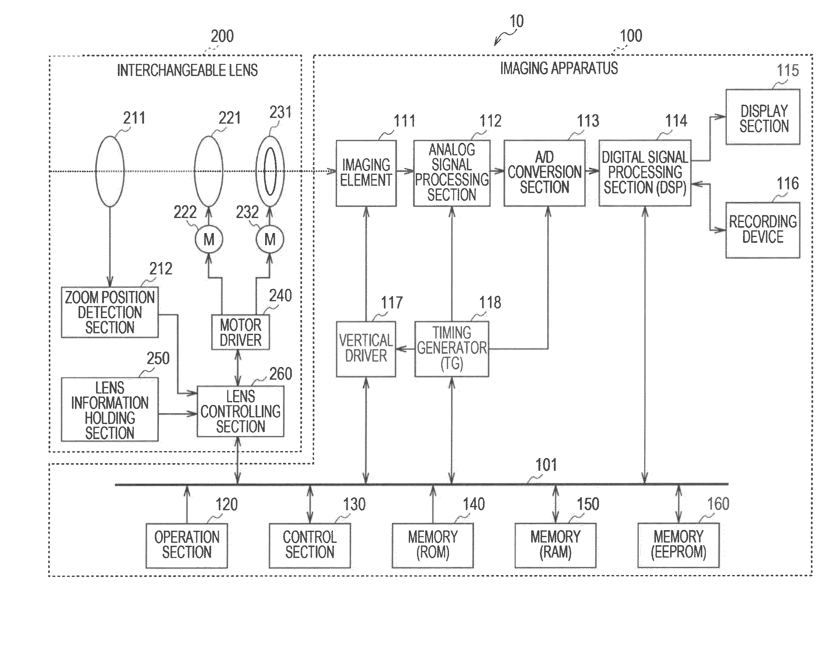
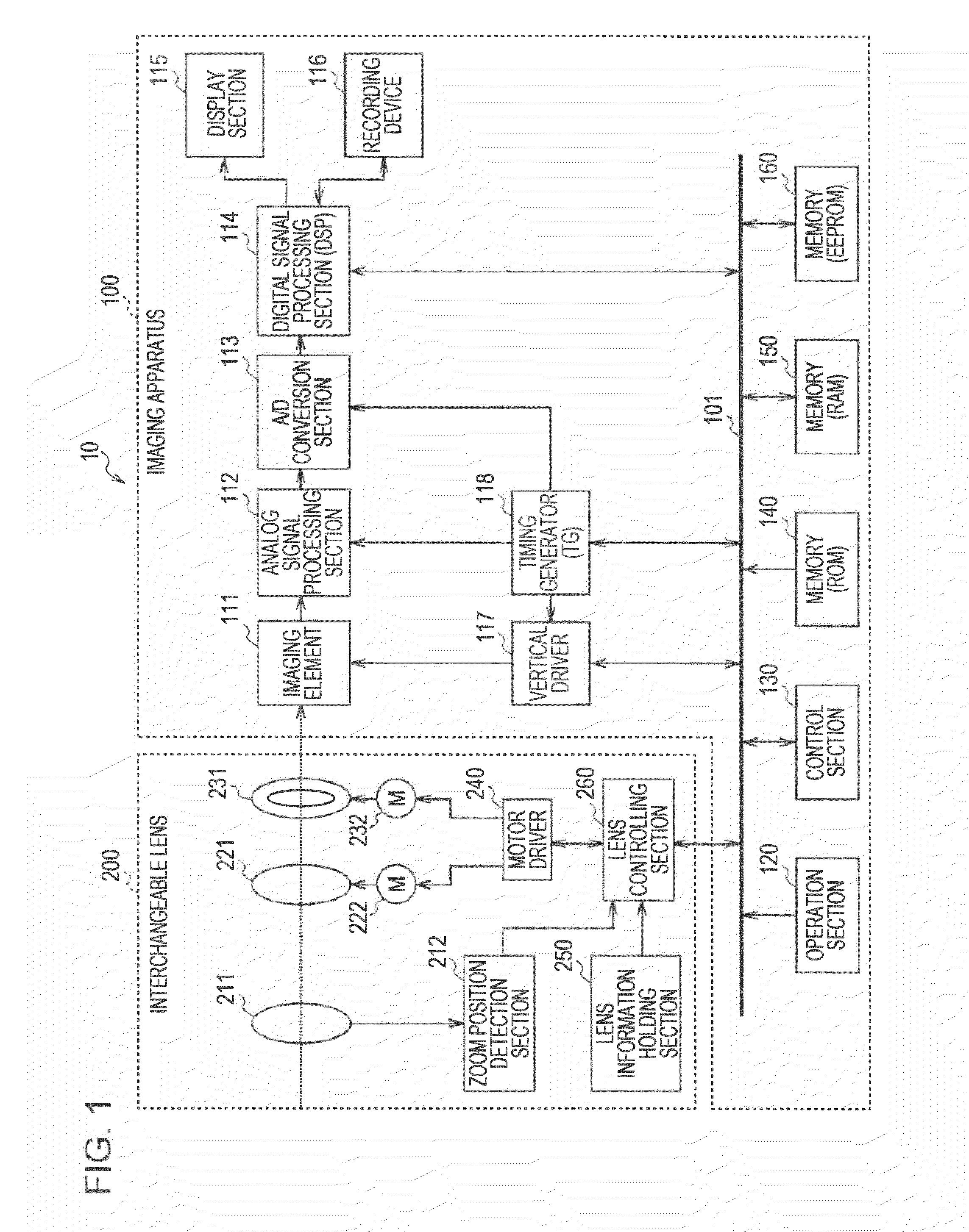
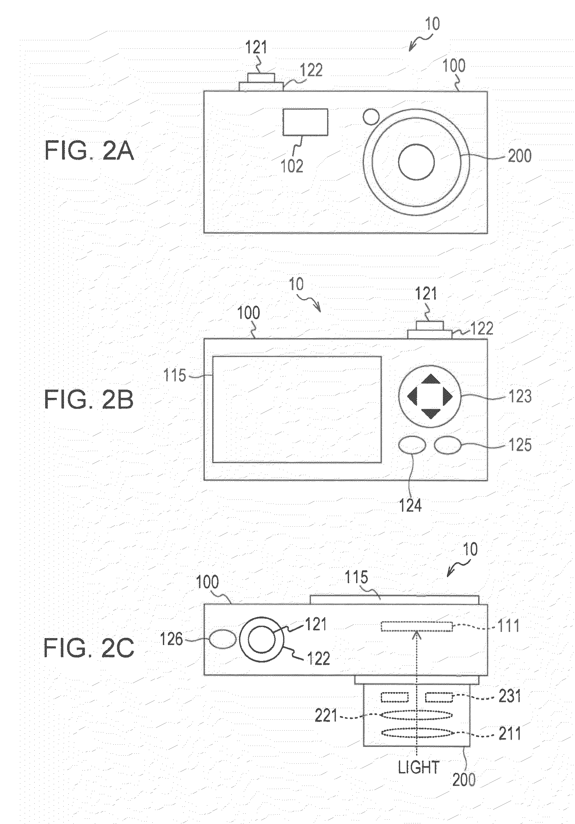
[0042]FIG. 1 is a block diagram illustrating an internal configuration example of an imaging system 10 according to a first embodiment of the invention. The imaging system 10 is provided with an imaging apparatus 100 and an interchangeable lens 200. It is possible to realize the imaging system 10 using, for example, a digital still camera where the lens is able to be interchanged (for example, a digital single-lens camera).
[0043]The imaging apparatus 100 is an imaging apparatus which images a subject, generates image data (imaging images), and records the generated image data as image content (still image content or moving image content). In addition, it is possible for the interchangeable lens 200 to be attached to the imaging image 100 via a lens mount (not shown).
[0044]The interchangeable lens 200 is an interchangeable lens unit which is attached to the imaging apparatus 100 via the lens mount (not shown). T...
second embodiment
2. Second Embodiment
[0156]In the first embodiment of the invention, an example is shown where the focusing target area (final selection area) is selected from the plurality of ranging areas arranged based on a constant regularity (for example, arranged in a 3×5 matrix formation) based on the subject distance and the MTF. Here, for example, in a case where a face is included in the imaging image, it is possible to set the ranging area with regard to the face. In addition, in a case where the imaging image includes a plurality of faces, each of the faces is detected and it is possible to set the ranging areas with regard to each of the detected faces. Therefore, in a case one of the ranging areas is selected from the ranging areas where there are the respective faces, it is possible to apply the first embodiment of the invention. Therefore, in a second embodiment, an example will be described where one of the ranging areas is selected from the ranging areas which are set with regard t...
third embodiment
3. Third Embodiment
[0166]In the first embodiment of the invention, an example is shown where the ranging area is selected in the imaging system 10 where an attachable and detachable type of the interchangeable lens 200 is mounted on the imaging apparatus 100. However, it is possible to apply the first embodiment of the invention to an imaging apparatus such as a digital still camera with a built-in lens. Therefore, in a third embodiment of the invention, an example will be described where the ranging area is selected in the imaging apparatus with a built-in lens. In addition, the configuration of the imaging apparatus according to the third embodiment of the invention is substantially the same as the example shown in FIGS. 1 to 3. As a result, in regard to members which are common with the first embodiment of the invention, the same reference numerals are attached and a portion of the description thereof (external configuration, functional configuration, and the like) is omitted.
[01...
PUM
 Abstract
Description
Claims
Application Information
 - R&D
- Intellectual Property
- Life Sciences
- Materials
- Tech Scout
- Unparalleled Data Quality
- Higher Quality Content
- 60% Fewer Hallucinations
Browse by: Latest US Patents, China's latest patents, Technical Efficacy Thesaurus, Application Domain, Technology Topic, Popular Technical Reports.
© 2025 PatSnap. All rights reserved.Legal|Privacy policy|Modern Slavery Act Transparency Statement|Sitemap|About US| Contact US: help@patsnap.com


