
Overcurrent protection circuit and overcurrent protection method

a protection circuit and protection method technology, applied in the direction of power conversion systems, dc-dc conversion, instruments, etc., can solve the problems of system adaptability to various, low change load conditions, and small effect of suppressing overcurrent, so as to reduce the start-up speed and prevent the switch element from deteriorating.

Active Publication Date: 2011-12-01
PANASONIC CORP
View PDF11 Cites 26 Cited by
  • Summary
  • Abstract
  • Description
  • Claims
  • Application Information

AI Technical Summary

Benefits of technology

"The present invention provides an overcurrent protection circuit and method for a switching power supply device that can effectively and easily suppress overcurrent over a wide load current range. The circuit includes a current detector and a controller that performs switching control based on the detected current. The controller includes an OFF period setting counter that determines the ON timing of the switching element based on the history of the current detection. The ON timing of the switching element is dynamically controlled based on the counter output, ensuring optimal performance and stability of the system. The circuit can be easily stabilized and can effectively suppress malfunctions caused by spike noise. The technical effect of the invention is to provide a reliable and effective overcurrent protection circuit for switching power supply devices."

Problems solved by technology

However, the overcurrent protection in the above conventional switching power supply devices has the following problems.
To be specific, in the overcurrent protection in the conventional switching power supply device described in Japanese Laid-Open Patent Application Publication No. 2007-20393, the problem is that system adaptability with respect to various, changing load conditions is extremely low.
For example, in a case where a predetermined delay period TDD1 with respect to a time constant of a switch current which increases in the minimum ON period is too short, the effect of suppressing the overcurrent becomes small, and the overcurrent protection function does not perform normally.
Therefore, the destruction and deterioration of the switching element occur.
In contrast, in a case where the predetermined delay period TDD1 with respect to the time constant of the switching current which increases in the minimum ON period is too long, electric power necessary to increase the output voltage VOUT1 up to a predetermined target value within a predetermined time cannot be adequately obtained at the time of the start-up or the like.
Therefore, a decrease in start-up speed or a start-up failure occurs.
Therefore, the switching current immediately exceeds the current threshold again, and the system is not stabilized.

Method used


Image

  • Overcurrent protection circuit and overcurrent protection method
  • Overcurrent protection circuit and overcurrent protection method
  • Overcurrent protection circuit and overcurrent protection method

Examples


Embodiment Construction

[0035]Hereinafter, an embodiment of a switching power supply device to which an overcurrent protection circuit according to the present invention is applied will be explained in reference to the drawings. Hereinafter, the same reference signs are used for the same or corresponding components in the drawings, and a repetition of the same explanation is avoided.

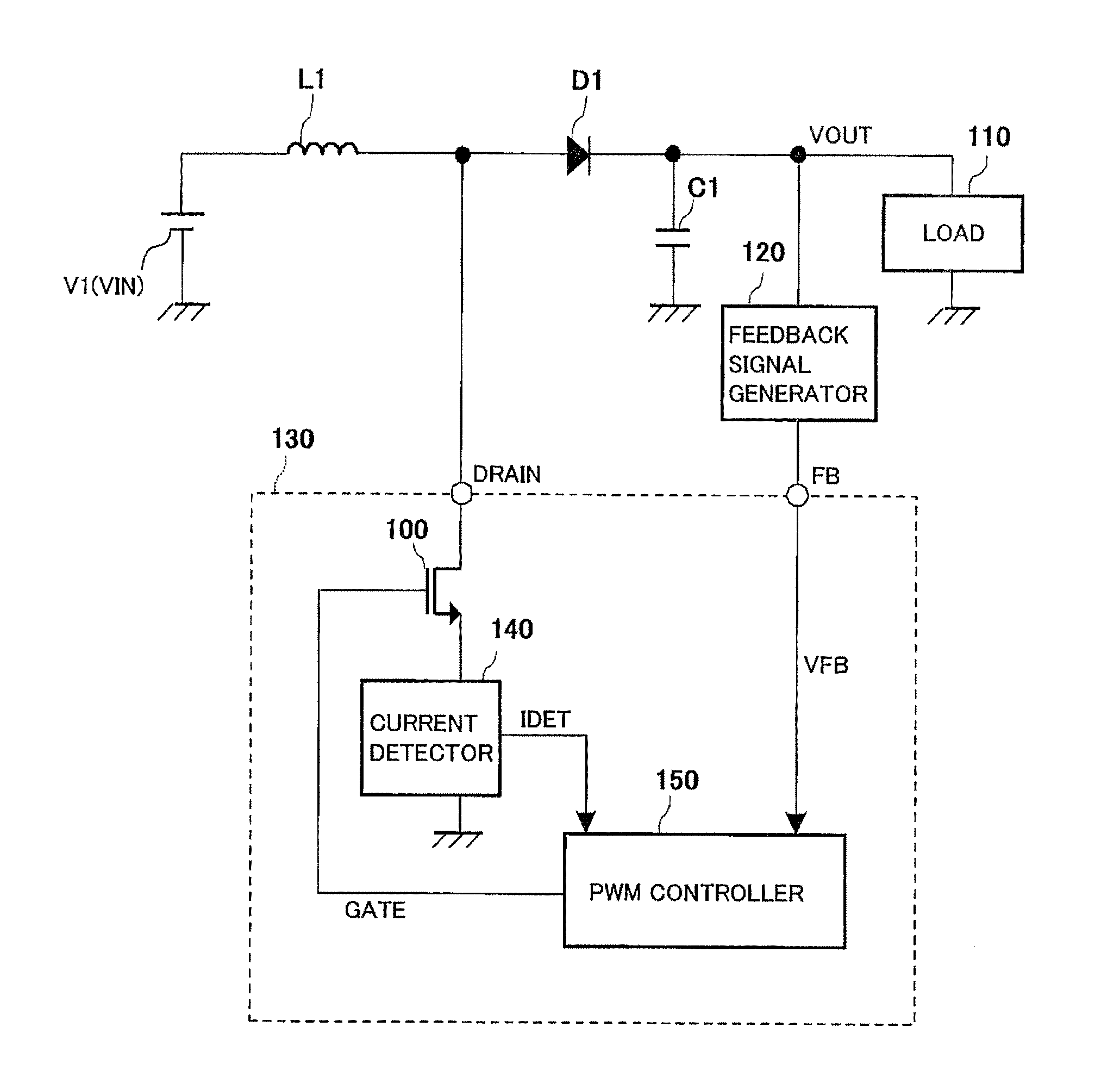
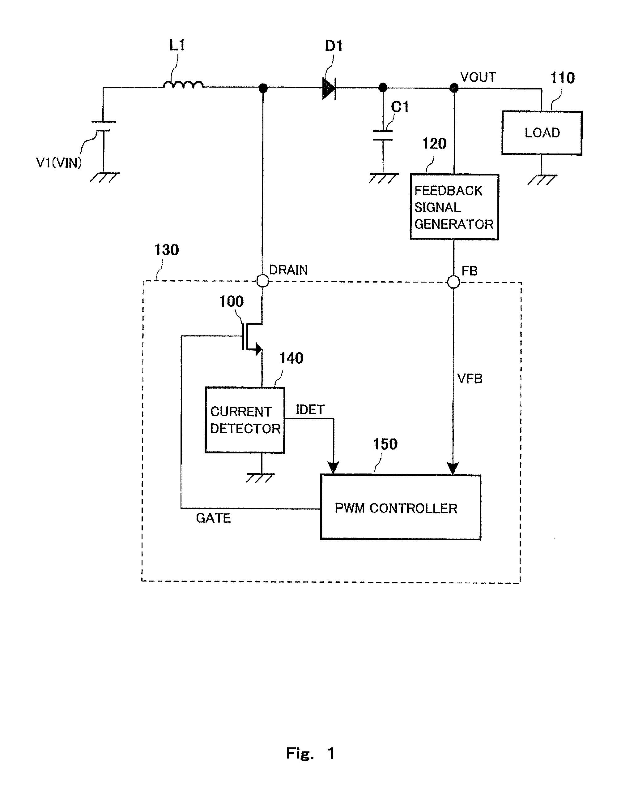
[0036]The switching power supply device to which the overcurrent protection circuit according to one embodiment of the present invention is applied will be explained in reference to FIGS. 1 to 4. FIG. 1 is a schematic circuit diagram showing an entire configuration example of the switching power supply device to which the overcurrent protection circuit according to one embodiment of the present invention is applied. As shown in FIG. 1, the switching power supply device includes: a power supply (voltage source) V1 configured to generate a power supply voltage VIN; a coil L1 connected to the power supply V1 and configured to stor...


PUM


Abstract

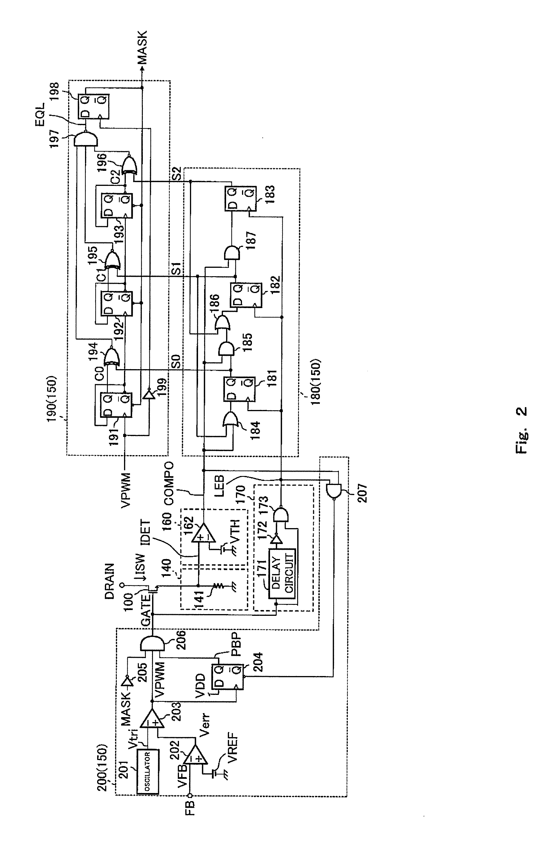
An overcurrent protection circuit includes: a determiner configured to determine whether or not the switch current exceeds a predetermined threshold, that is, the switch current is an overcurrent state when the switching element is turned ON; an OFF period setting counter configured to increase or decrease a counter output depending on a determination result of the determiner; and a drive signal generator configured to generate a drive signal of the switching element such that a length of an ON timing interval of the switching element corresponds to the counter output of the OFF period setting counter.

Description

CROSS REFERENCE TO RELATED APPLICATION[0001]The disclosures of Japanese Patent Applications No. 2010-123378 filed on May 28, 2010 and No. 2011-053238 filed on Mar. 10, 2011 each including a specification, drawings and claims are incorporated herein by reference in their entirety.BACKGROUND OF THE INVENTION[0002]1. Field of the Invention[0003]The present invention relates to an overcurrent protection circuit and an overcurrent protection method, each of which prevents an overcurrent from flowing through a switching element.[0004]2. Description of the Related Art[0005]Generally, a switching control device, such as a switching power supply device, includes an overcurrent protection circuit for the purpose of protecting a switching element from destruction and deterioration. A general overcurrent protection method is a method for: detecting a current flowing through the switching element; when the detected current is higher than a predetermined threshold, determining that the current is...

Claims


Application Information

Patent Timeline
Patent Type & Authority Applications(United States)
IPC IPC(8): G05F1/618
CPCH02M1/32H02M2001/0009H02M3/156H02M1/0009
Inventor TAKATA, GOYAMAMOTO, YASUNORI
Owner PANASONIC CORP
Learn More