
Robotically-controlled shaft based rotary drive systems for surgical instruments

a robotic drive and surgical instrument technology, applied in the field of surgical staplers, can solve the problems of not affording the surgeon an opportunity, the device that performs both functions in the same trigger actuation is often exceedingly difficult to operate, and the surgeon is not able to partially retract the cutting member, etc., to achieve the effect of quick and convenient selection

Active Publication Date: 2011-12-01
CILAG GMBH INT
View PDF0 Cites 743 Cited by
  • Summary
  • Abstract
  • Description
  • Claims
  • Application Information

AI Technical Summary

Benefits of technology

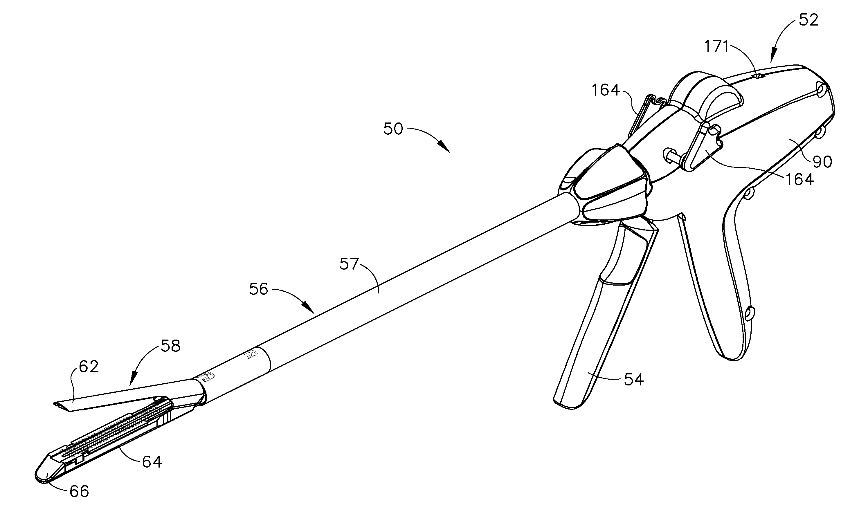
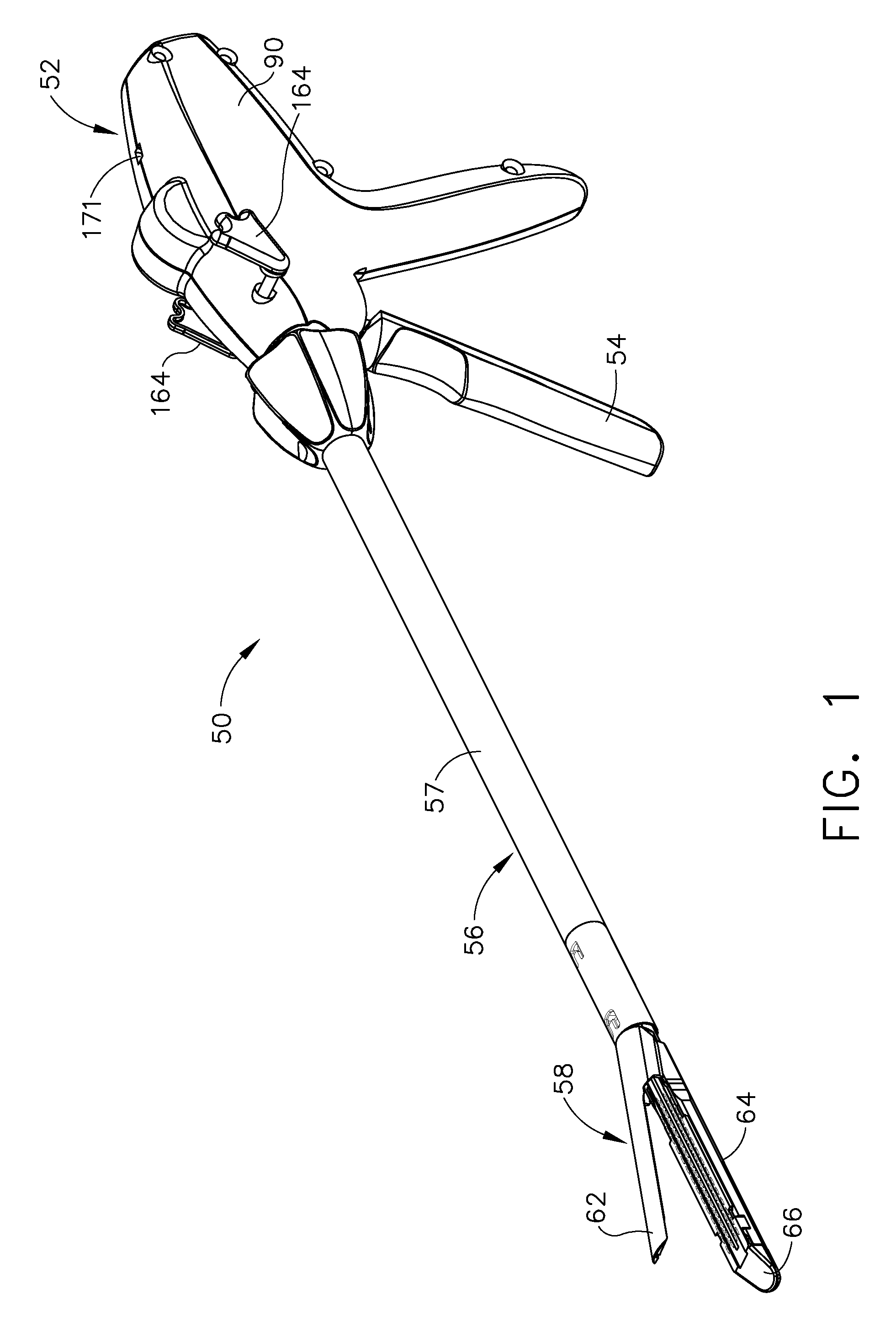
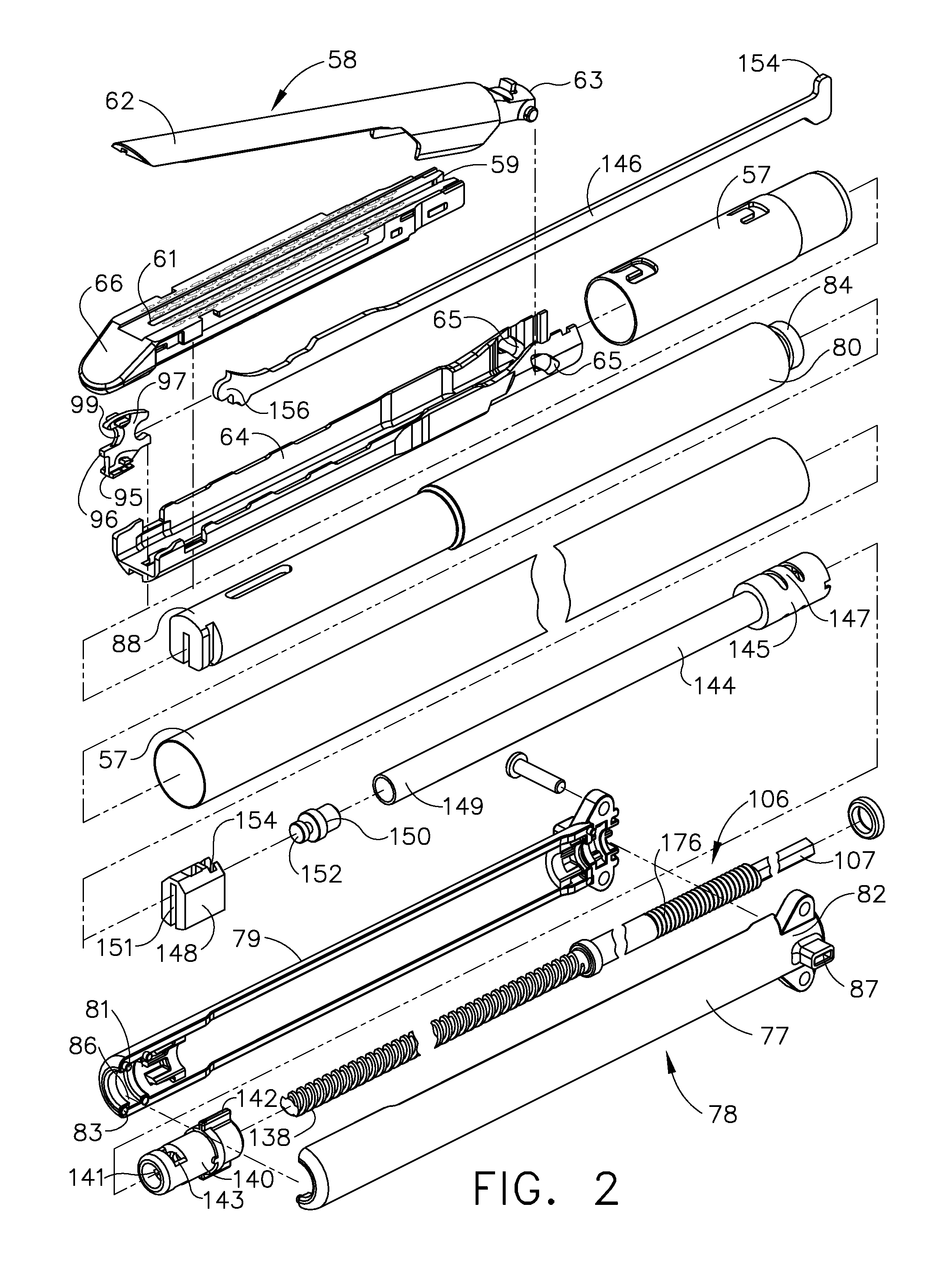
In at least one form of the invention, a surgical instrument can include a switching mechanism which can allow a surgeon, or other clinician, to selectively advance or retract a staple driver and / or cutting member within a staple cartridge. In various embodiments, the surgical instrument can include a handle, a trigger operatively coupled to the handle, a firing drive, and an end effector. In at least one embodiment, the firing drive can include a first ratchet assembly configured to advance a cutting member in the end effector and a second ratchet assembly configured to retract the cutting member. In various embodiments, the trigger can include first and second pawls pivotably mounted thereon which are configured to be selectively engaged with the first and second ratchet assemblies, respectively. In at least one such embodiment, the trigger can be configured to slide between a first position in which the first pawl is engaged with the first ratchet assembly and a second position in which the second pawl is engaged with the second ratchet assembly. In such embodiments, a surgeon can quickly and conveniently select between advancing and retracting motions of the cutting member.
In at least one form of the invention, a surgical instrument can include a trigger which can be configured to close a jaw member onto soft tissue, for example, upon a first actuation of the trigger and advance a staple driver and / or cutting member upon a subsequent, or second, actuation of the trigger. In various embodiments, such a surgical instrument can allow a surgeon to position the surgical instrument in a surgical site and close the jaw member with an initial actuation of the trigger without deploying any staples into, or incising, the tissue. In such embodiments, as a result, the surgeon can manipulate the position of the surgical instrument and then actuate the trigger a second time to deploy staples into, and / or incise, the tissue. In at least one such embodiment, the first actuation of the trigger which closes the jaw member can also unlock a firing drive configured to advance the staple driver and cutting member during the second actuation of the trigger. In various embodiments, the surgical instrument can include a switching mechanism which can allow the surgeon to reopen the jaw member and, if they so choose, to reposition the jaw member in a more suitable position.

Problems solved by technology

Such staplers, however, are unable to partially retract the cutting member and, as a result, the cutting member must be fully retracted before it can be readvanced.
While suitable in some circumstances, devices which perform both functions in the same trigger actuation are often exceedingly difficult to operate owing to the high degree of force required to actuate the trigger.
Furthermore, such devices, as they close the jaw member and deploy staples in the same trigger actuation, do not afford the surgeon with an opportunity to evaluate the position of the closed jaw member and reposition the jaw member before the staples are deployed into the soft tissue.

Method used


Image

  • Robotically-controlled shaft based rotary drive systems for surgical instruments
  • Robotically-controlled shaft based rotary drive systems for surgical instruments
  • Robotically-controlled shaft based rotary drive systems for surgical instruments

Examples


Embodiment Construction

Applicant of the present application also owns the following patent applications that have been filed on even date herewith and which are each herein incorporated by reference in their respective entireties:

U.S. patent application Ser. No. ______, entitled “Surgical Instrument With Wireless Communication Between a Control Unit of a Robotic System and Remote Sensor”, Attorney Docket No. END5924USCIP2 / 060339CIP2;

U.S. patent application Ser. No. ______, entitled “Robotically-Controlled Disposable Motor Driven Loading Unit”, Attorney Docket No. END6213USCIP1 / 070330CIP1;

U.S. patent application Ser. No. ______, entitled “Robotically-Controlled Endoscopic Accessory Channel”, Attorney Docket No. END5568USCIP2 / 100809CIP2;

U.S. patent application Ser. No. ______, entitled “Robotically-Controlled Motorized Surgical Instrument”, Attorney Docket No. END6416USCIP1 / 080205CIP1;

U.S. patent application Ser. No. ______, entitled “Robotically-Controlled Surgical Stapling Devices That Produce Formed Stap...


PUM

PropertyMeasurementUnit
distanceaaaaaaaaaa
degree of forceaaaaaaaaaa
torqueaaaaaaaaaa

Abstract

A surgical instrument including an end effector that has a selectively reciprocatable implement movably supported therein. The implement is selectively advanceable in a distal direction upon application of a rotary actuation motion thereto and retractable in a proximal direction upon application of a rotary retraction motion thereto. An elongate shaft assembly is coupled to the end effector and is configured to transmit the rotary actuation motion and rotary retraction motion to the reciprocatable implement from a robotic system that is configured to generate the rotary actuation motion and said rotary retraction motion.

Description

BACKGROUND1. Field of the InventionThe present invention generally relates to surgical stapling instruments and, more particularly, to surgical staplers having an end effector closing system and a firing system for deploying staples.2. Description of the Related ArtAs known in the art, surgical staplers are often used to deploy staples into soft tissue to reduce or eliminate bleeding from the soft tissue, especially as the tissue is being transected, for example. Surgical staplers, such as an endocutter, for example, often comprise an end effector which is configured to secure the soft tissue between first and second jaw members. The first jaw member often includes a staple cartridge which is configured to removably store staples therein and the second jaw member often includes an anvil. In use, the staples are typically deployed from the staple cartridge by a driver which traverses a channel in the staple cartridge and causes the staples to be deformed against the anvil and secure ...

Claims


Application Information

Patent Timeline
Patent Type & Authority Applications(United States)
IPC IPC(8): A61B17/068
CPCA61B2017/2943A61B2017/0688A61B19/026A61B2017/07271A61B19/0287A61B2017/2923A61B2017/00734A61B2017/00685A61B19/2203A61B2017/00473A61B17/320068A61B2017/00115A61B17/07207A61B2017/07278A61B2017/00398Y10T29/53A61B2019/4857A61B34/30A61B2017/00477A61B2017/2927A61B2017/2933A61B2017/2937A61B2017/2905A61B2017/07285A61B2090/0811A61B2090/0803A61B17/072A61B2017/00314A61B2017/00323A61B18/1445A61B2018/1455A61B50/30A61B50/36A61B2017/320069A61B2017/320071A61B2034/302A61B17/00234A61B17/068A61B17/0684A61B17/105A61B17/32A61B2017/00367A61B2017/07257
Inventor TIMM, RICHARD W.SHELTON, IV, FREDERICK E.
Owner CILAG GMBH INT
Learn More