Proximity type antenna and radio communication device
- Summary
- Abstract
- Description
- Claims
- Application Information
AI Technical Summary
Benefits of technology
Problems solved by technology
Method used
Image
Examples
first embodiment
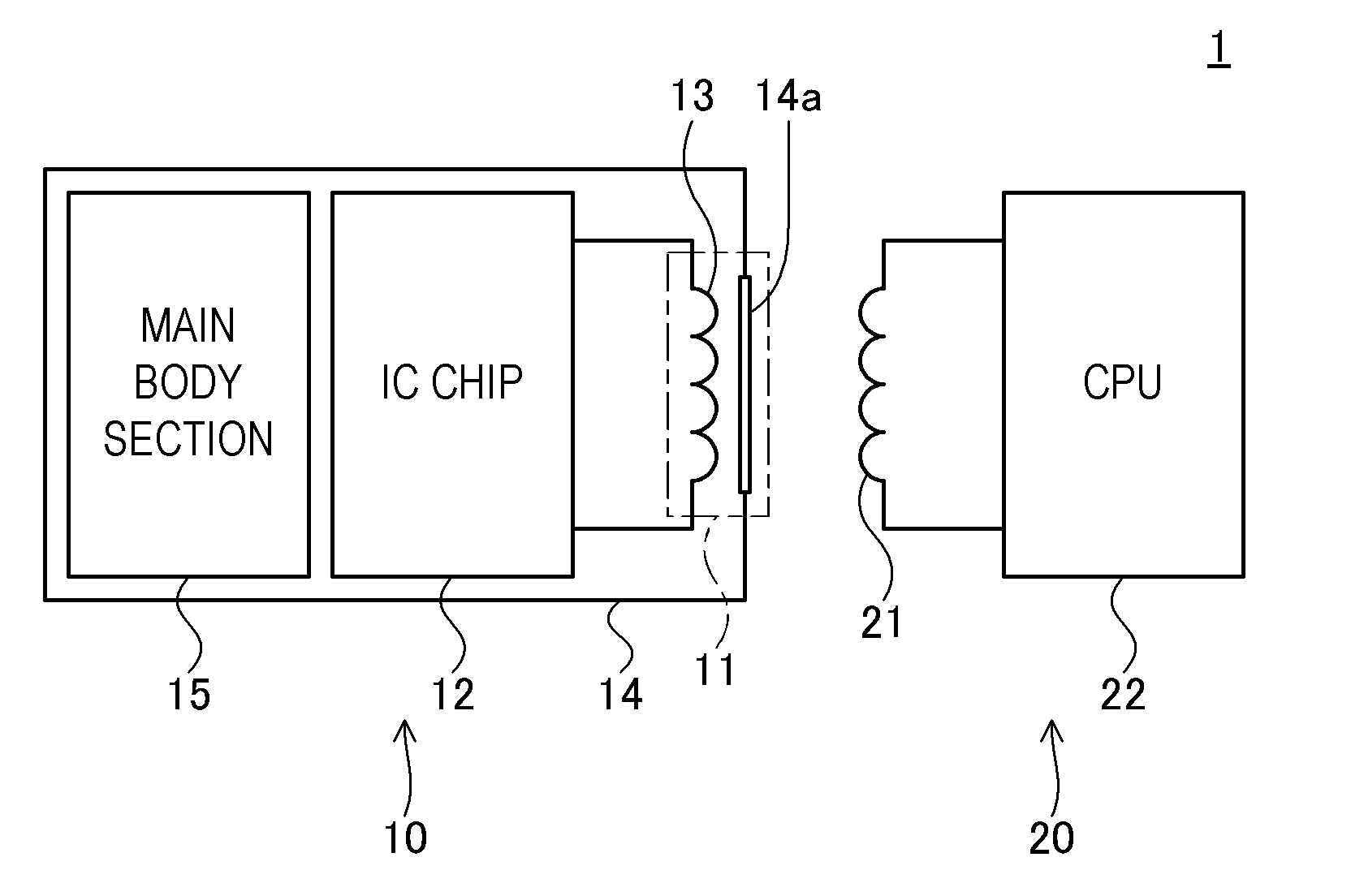
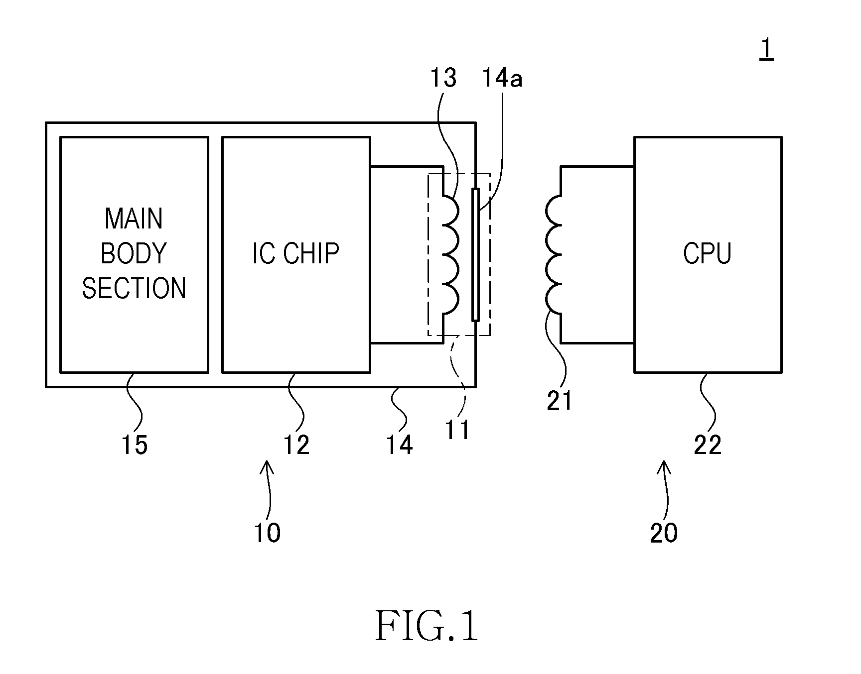
[0142]FIG. 1 is a schematic illustration of a short distance communication system 1 according to the present invention, showing the system configuration thereof. As shown in FIG. 1, the short distance communication system 1 includes a mobile phone 10 (radio communication apparatus) that includes a proximity type antenna 11, an IC chip 12 and a main body section 15 and a reader / writer 20 (external communication apparatus) that includes a proximity type antenna 21 and a CPU 22. The proximity type antenna 11 and the IC chip 12 mounted in the mobile phone 10 are components of a non-contact type IC card.
[0143]The short distance communication system 1 may typically be a MIFARE (registered trademark) or a Felica (registered trademark), which is a system for writing data into a memory (not shown) in the IC chip 12 and reading data from the memory by means of the reader / writer 20.
[0144]Communication between the mobile phone 10 as a non-contact type IC card and the reader / writer 20 is realize...
third embodiment
[0210]FIG. 20A is a schematic perspective view of a mobile phone 10 to be used in a short distance communication system according to the present invention. FIG. 20B is a cross-sectional view taken along line A-A′ in FIG. 20A. FIG. 21 is an enlarged schematic view of part of the mobile phone 10 of FIG. 20A showing a slit SL and an aperture OP and the vicinity thereof, which will be described in greater detail hereinafter. The conductive plate 14a is hatched in FIG. 20A as in FIG. 20B for easy understanding, although FIG. 20A is not a cross-sectional view. The above description also applies to views that will be described hereinafter.
[0211]The short distance communication system according to this embodiment is same as the one according to the first embodiment except that only the mobile phone 10 thereof differs from that of the first embodiment. As shown in FIGS. 20A and 20B, the mobile phone 10 of this embodiment is substantially a rectangular parallelepiped and an LCD 50 and a keypa...
sixth embodiment
[0255]FIG. 32A is a schematic perspective view of a mobile phone 10 to be used in a short distance communication system according to the present invention. FIG. 32B is a cross-sectional view taken along line A-A′ in FIG. 32A. FIG. 33 is an enlarged schematic view of part of the mobile phone 10 of FIG. 32A showing a second slit SL2 and the vicinity thereof, which will be described in greater detail hereinafter. The conductive plate 14a is hatched in FIG. 32A as in FIG. 32B for easy understanding, although FIG. 32A is not a cross-sectional view. The above description also applies to views that will be described hereinafter.
[0256]The short distance communication system according to this embodiment is same as the one according to the first embodiment except that only the mobile phone 10 thereof differs from that of the first embodiment. As shown in FIGS. 32A and 32B, the mobile phone 10 of this embodiment is substantially a rectangular parallelepiped and an LCD 50 and a keypad 51 are ar...
PUM
 Abstract
Description
Claims
Application Information
 - R&D
- Intellectual Property
- Life Sciences
- Materials
- Tech Scout
- Unparalleled Data Quality
- Higher Quality Content
- 60% Fewer Hallucinations
Browse by: Latest US Patents, China's latest patents, Technical Efficacy Thesaurus, Application Domain, Technology Topic, Popular Technical Reports.
© 2025 PatSnap. All rights reserved.Legal|Privacy policy|Modern Slavery Act Transparency Statement|Sitemap|About US| Contact US: help@patsnap.com


