LED analog clock or watch display

an analog clock and watch technology, applied in the field of led analog clocks or watch displays, can solve the problems of difficult discerning of the current time, difficulty in determining the correct time, and inability to intuitively know what the lights represent, so as to quickly identify the current time and quickly deduce the current time

Inactive Publication Date: 2011-11-24
REINGOLD PHILLIP
View PDF13 Cites 1 Cited by
  • Summary
  • Abstract
  • Description
  • Claims
  • Application Information

AI Technical Summary

Benefits of technology

[0014]By combining these five improvements, one can view the clock or watch face whether night or day and quickly deduce the current time. In resolving the time, the viewer would look at the portion of the Ellipse or Circle illuminated, the largest 90 Degree increment Light that is illuminated and at most count 2 increments past that position to identify the current Hour and with the separate Ellipse or Circle for Minutes in a similar manner to the current Hour the current 5 minute increment can be readily identified quickly.

Problems solved by technology

The number of elements and the need to discern the correct time is difficult due to the density of elements within the clock or watch face.
The density of the sixty red LED's representing the current minute illuminated in sequence to mimic a clock hand makes the discerning of the current time difficult to determine.
This is evident especially in the dark or at large distance from the clock where the other non-illuminated portion of the clock face is unlit or in the case of the binary lights, the viewer does not intuitively know what the lights represent.
Deviation from the familiar analog clock face maybe unique in prior art, but does not provide the necessary intuitive recognition of time at a glance.

Method used


Image

  • LED analog clock or watch display
  • LED analog clock or watch display
  • LED analog clock or watch display

Examples


Embodiment Construction

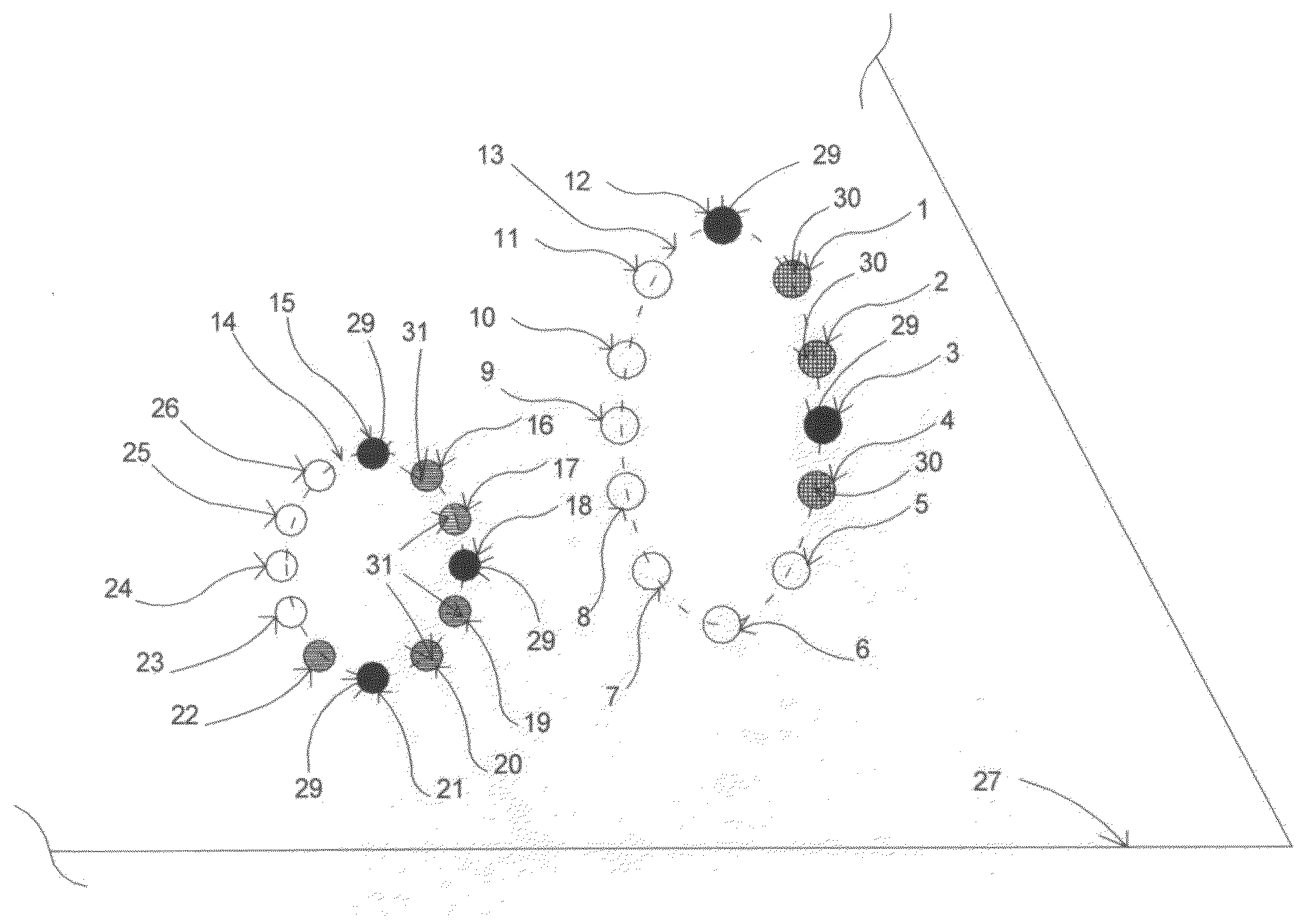
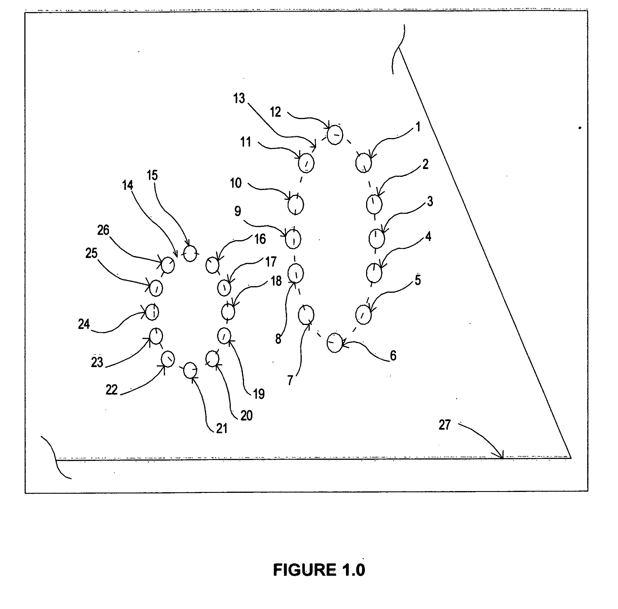
[0020]The present invention is defined per FIG. 1 as two separate Ellipses or Circles 13&14 that represent Hours and Minutes of time respectively that are within the same Clock Face 27 or on separate Clock Faces 27&28 per FIG. 3. The shape of each Clock Face can be triangular or rectangular or circular or an irregular shape. The separation of the Hour's Ellipse or Circle and the Minute's Ellipse or Circle is critical to the use of light to represent the current time.

[0021]The Hours are present in ellipse or circle 13 and Minutes are present in ellipse or circle 14. The hour positions are identified within FIG. 1 as circle 1 to circle 12 representing 1 o'clock to 12 o'clock respectively. The Minute positions are identified within FIG. 1 as circle 15 to circle 26 representing 0 minutes to 55 minutes respectively in 5-minute increments.

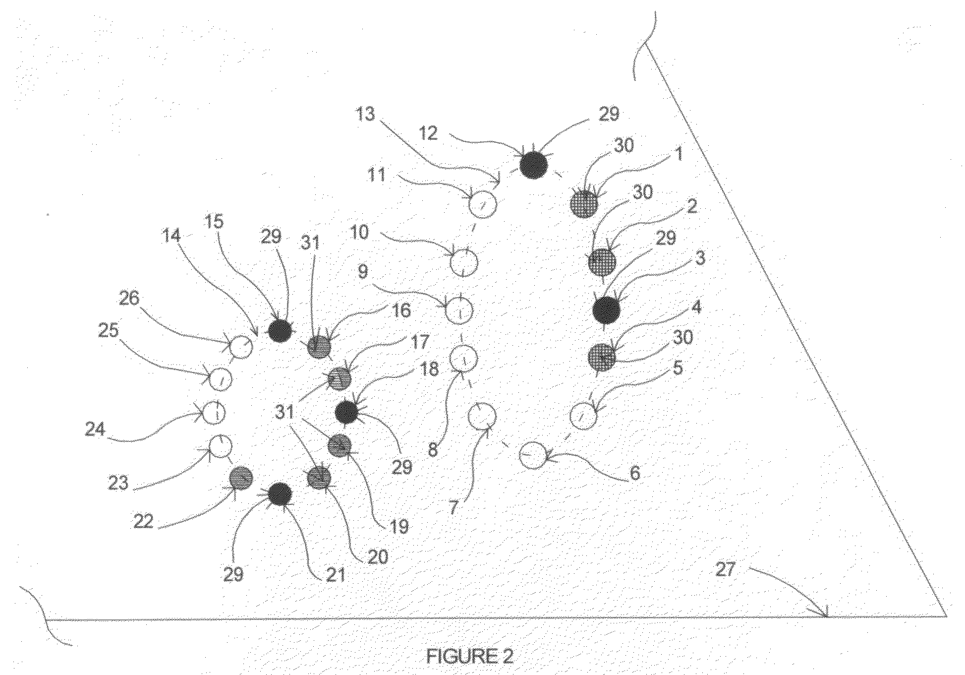
[0022]Referring to FIG. 2, the operation of the present invention is illustrated by illumination of the 12 o'clock, 1 o'clock, 2 o'clock, 3 o'clock and ...


PUM


Abstract

The Clock Face or Watch Face contains two physically separate and non-concentric circles of Light representing Hours and Minutes and an Arc representing Seconds. The Hours fill in 12 smaller circles with Light as the Hours pass and the Minutes fill in 12 smaller circles with Light as 60 minutes pass.The differentiation of LED Colors within a circle of Light allows the viewer to easily determine the Light filled Section of each Larger Ellipse or Circle for the current Hour or Minute. The use of a distinct LED or Light color for the 90 Deg increments within an Ellipse or Circle eliminates or reduces the need to count circles of Light to quickly identify the current time. The 12 o'clock, 3 o'clock, 6 o'clock and 9 o'clock positions are on 90 Deg Increments and have a separate distinct Light color from the other Lighted positions within the Hour's Ellipse or Circle.

Description

REFERENCE CITED: US PATENT DOCUMENTS[0001]U.S. Ser. No. 61 / 216,617May 2009Phillip ReingoldD453,114July 2001Phillip Reingold4,920,524April 1990Kotob4,254,487March 1981Lee3,958,409May 1976Manber3,841,082October 1974CuevasFIELD OF THE INVENTION[0002]This invention relates to an LED Analog Clock or Watch Display. The Display uses a distinct and novel approach without the use of Clock Hands or Digits to allow the viewer to quickly determine the current time. The use of Lights along with separate Ellipses or Circles gives the viewer an intuitive illumination of Time using 3 or 4 different LED Colors. Each LED Color clarifies simply to the viewer what the current time is. The Seconds Arc or Line is made up of 5 to 30 smaller circles representing the passage or seconds or time passing by. Further, the invention uses within each of the two Larger Ellipse or Circles 3 to 4 distinct Light or LED Colors combined with the filling in of each of the larger Ellipses or Circles of Light or LEDS to g...

Claims


Application Information

Patent Timeline
Patent Type & Authority Applications(United States)
IPC IPC(8): G04C17/00
CPCG04G9/042
Inventor REINGOLD, PHILLIP STANLEY
Owner REINGOLD PHILLIP
Why Eureka
Try Eureka