
In-wheel switched reluctance motor drive

a technology of reluctance motor and in-wheel drive, which is applied in the direction of motor/generator/converter stopper, electric propulsion mounting, dynamo-electric converter control, etc., and can solve problems such as direct wheel rotation

Active Publication Date: 2011-11-24
THE HONG KONG POLYTECHNIC UNIV
View PDF8 Cites 23 Cited by
  • Summary
  • Abstract
  • Description
  • Claims
  • Application Information

AI Technical Summary

Problems solved by technology

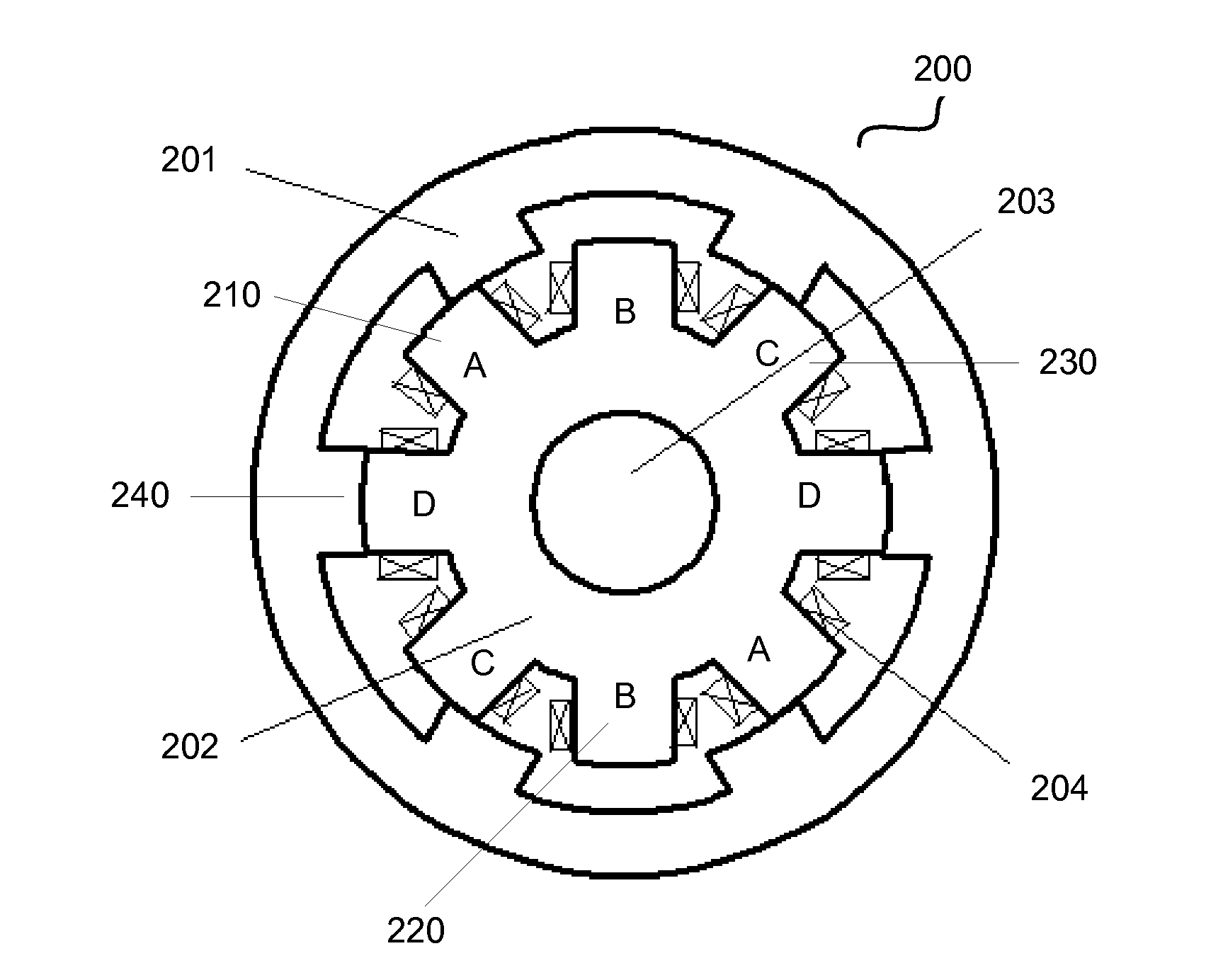
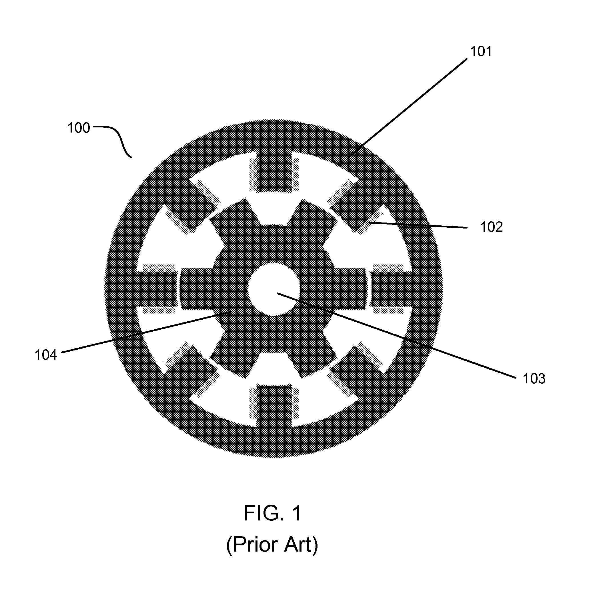
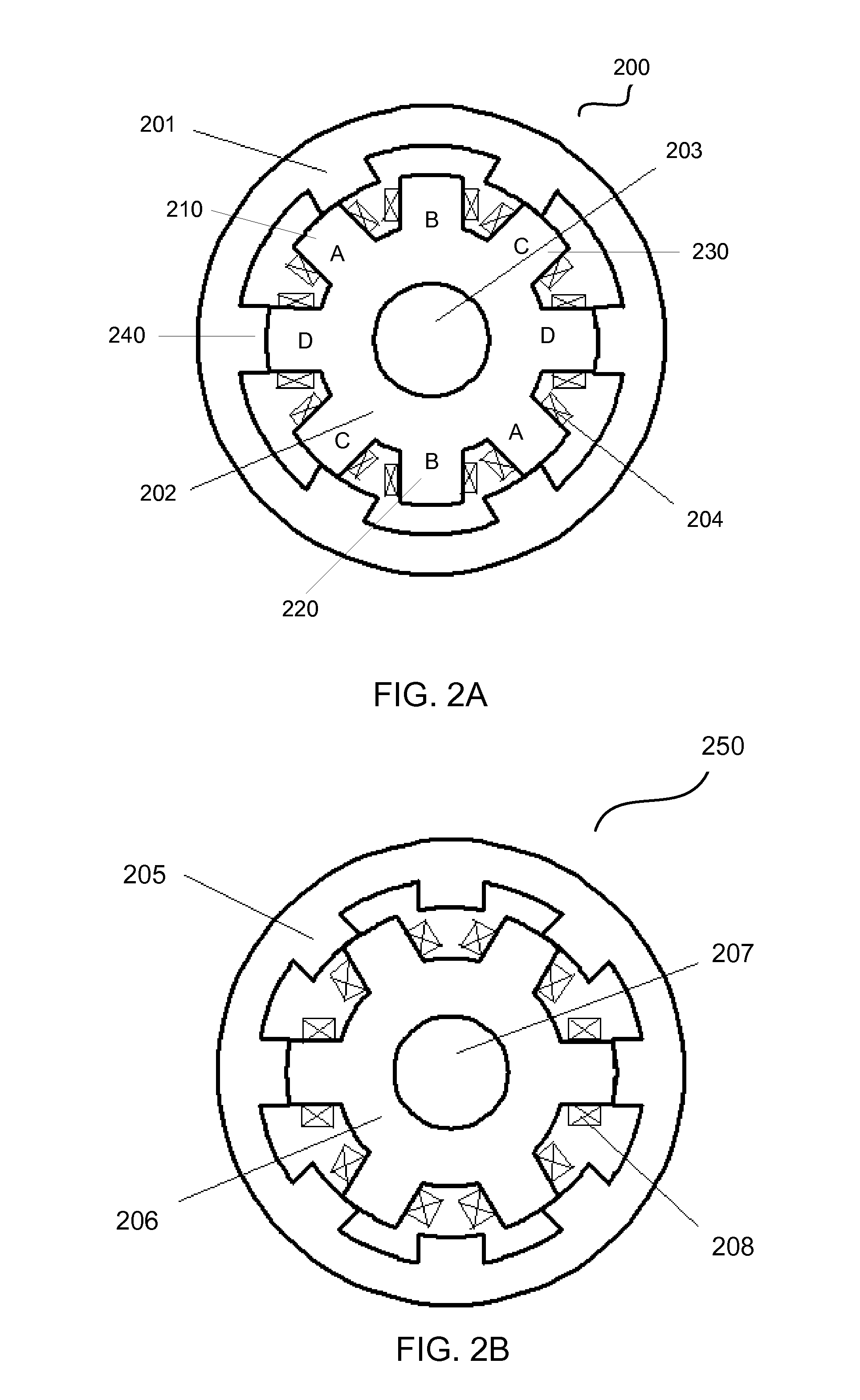
However, since the rotor of a conventional SRM is located inside of the stator, the rotation of the rotor cannot directly lead to the rotational of a wheel when it is used in an in-wheel design.

Method used


Image

  • In-wheel switched reluctance motor drive
  • In-wheel switched reluctance motor drive
  • In-wheel switched reluctance motor drive

Examples


example

[0071]In this example, two 5 kW in-wheel SRMs are determined to directly drive EV wheels. From the discussion in the last section, the design requirements are proposed as follows.

[0072]Rated power=5 kW

[0073]Number of phases=4

[0074]Number of stator poles=8

[0075]Number of rotor poles=6

[0076]Rated motor speed=1000 rpm

[0077]DC link voltage=240 V

[0078]Taking account of the constrains on the stator pole arc angle and rotor pole arc angle, which are given by the equations from (17) to (22), the stator pole arc angle has to be confine as

18s<22.5  (24)

[0079]Consequently, the rotor pole arc angle has to be selected in the range, given as

18r<27  (25)

Defining the stator and rotor pole arc angles in degree in integers, the stator and rotor pole arc angles for the present design requirements must vary with the specified values, which are shown in Table I.

TABLE IVALUES OF STATOR AND ROTOR POLE ARC ANGLESβs (degree)βr (degree)1920, 21, 222021, 22, 23, 242122, 23, 24, 252223, 24, 25, 26

[0080]The obt...


PUM


Abstract

A switched reluctance motor includes an inner stator having a plurality of stator poles with coil windings, the inner stator having a plurality of stator phases, an outer rotor configured to rotate around the inner stator, the outer rotor having a plurality of rotor poles, at least one position sensor configured to detect a position of the outer rotor, and a DC supply configured to sequentially supply current to excite the stator phases.

Description

BACKGROUND OF THE INVENTION[0001]1. Field of the Invention[0002]The present invention relates to electric motors, more particularly, to switched reluctance motors.[0003]2. Description of the Related Art[0004]Electric motors, along with power electronics technologies, play an important role in the development of Electric Vehicles (EV). In EV applications, electric motors are desired to have a high starting torque for initial acceleration, high torque density and high efficiency to extend battery life. Consequently, design of an electric motor for EV has to address to the above needs.[0005]Recent advances in power electronic technologies have made Switched Reluctance Motor (SRM) an attractive candidate for Electric Vehicle (EV) due to advantages such as simple and rugged motor construction, low weight, low manufacturing cost, easy cooling, excellent power-speed characteristics, high torque density, high operating efficiency, inherent fault tolerance, direct-drive, high transmission ef...

Claims


Application Information

Patent Timeline
Patent Type & Authority Applications(United States)
IPC IPC(8): B60K1/00H02P6/08H02K37/02
CPCH02P25/08B60K7/0007
Inventor CHENG, KA WAI ERICXUE, XIANGDANGCHEUNG, CHOW NORBERT
Owner THE HONG KONG POLYTECHNIC UNIV
Learn More