
Method for Determining Paths of Particle Beams Through 3D Tissue Volumes

Active Publication Date: 2011-11-17
MITSUBISHI ELECTRIC CORP
View PDF10 Cites 19 Cited by
  • Summary
  • Abstract
  • Description
  • Claims
  • Application Information

AI Technical Summary

Benefits of technology

[0009]Considering the problem from the point of view of an actual treatment enables us to formulate path heuristics, which ar

Problems solved by technology

Considering the problem from the point of view of an actual treatment enables us to formulate path heuristics, which are typically difficult to enforce in the conventional TSP solver.

Method used


Image

  • Method for Determining Paths of Particle Beams Through 3D Tissue Volumes
  • Method for Determining Paths of Particle Beams Through 3D Tissue Volumes
  • Method for Determining Paths of Particle Beams Through 3D Tissue Volumes

Examples


Embodiment Construction

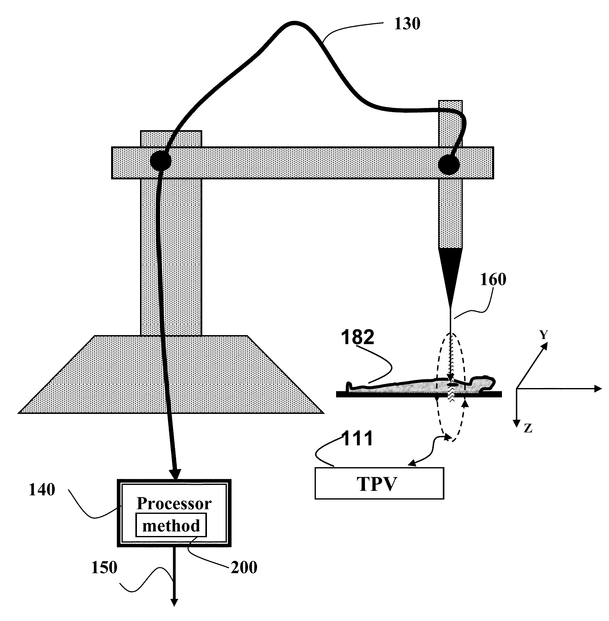
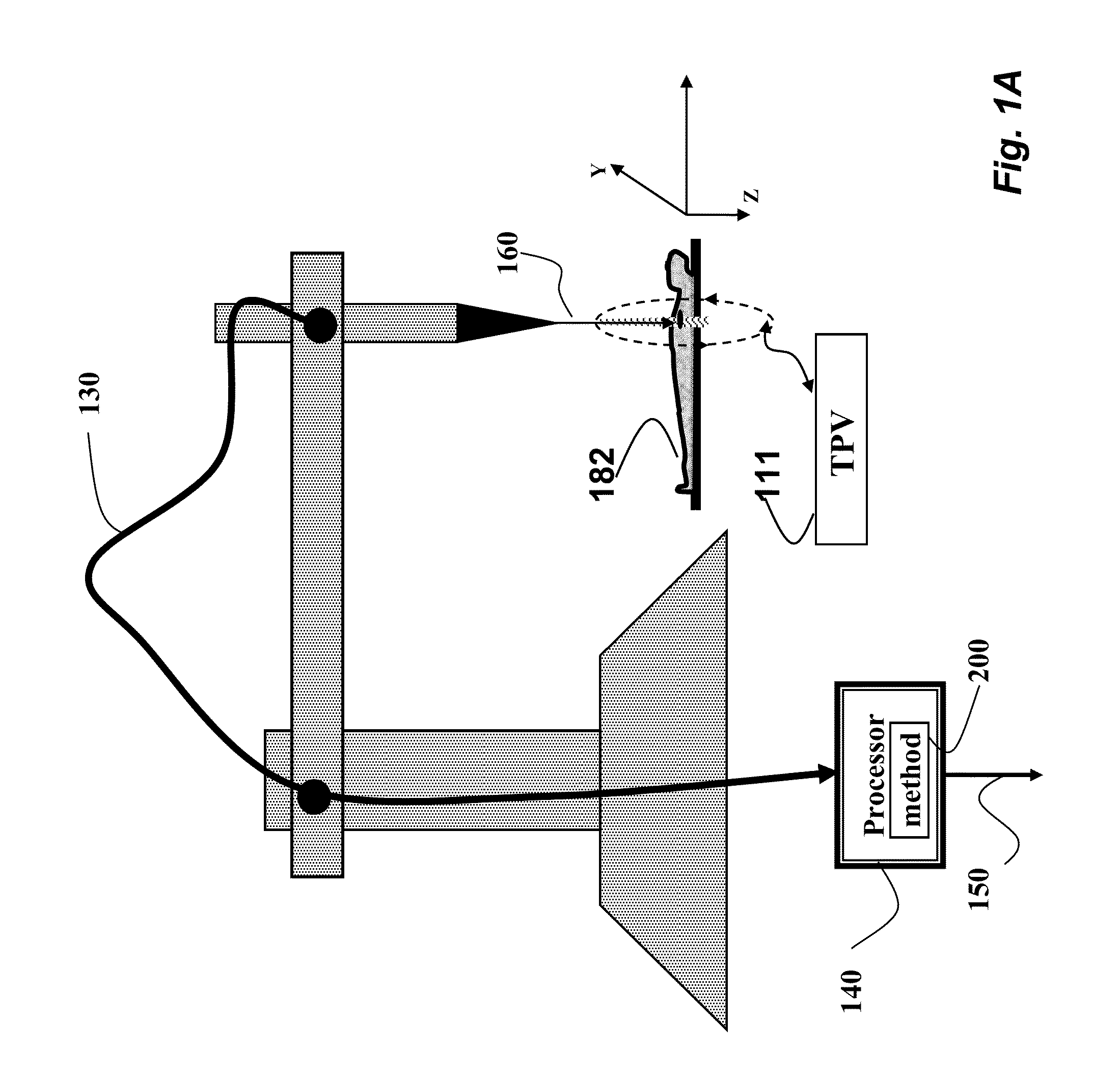
[0042]FIG. 1A shows a system and a method 200 for determining a path 150 of a radiotherapy particle beam 160 through a 3D treatment planning volume (TPV) 111, e.g., tissue of a patient 182. However, embodiments of the invention determine a path through any type of 3D and / or 2D volumes. The method 200 is executed by a processor 140 as known in the art. The TPV is partitioned into a set of slices. The slices are substantially coplanar. In practice, the slices are aligned according to the iso-energies of the beam.

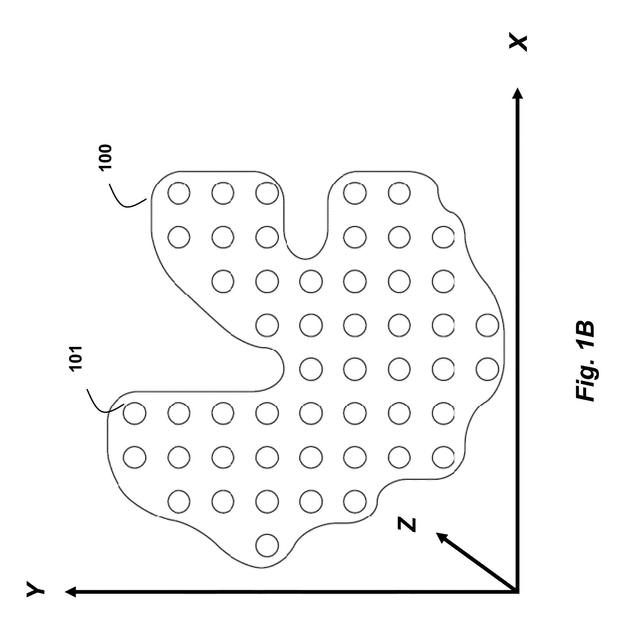
[0043]FIG. 1B shows one such slice 100 that is substantially orthogonal to the beam. That, is the slices are in the mostly XY (planar) direction, and the beam is in a Z (depth) order. Herein, the notation {.} designates sets.

[0044]The embodiments of the invention are based on a realization that, for any slice, the particle beam moves faster in one direction, i.e., the selected direction, then in another. Accordingly, the embodiments of the invention acquire the selected direct...


PUM


Abstract

A path of a particle beam is determined through a 3D planning treatment volume (PTV), wherein the PTV includes a set of slices in a depth order, and each slice includes a set of locations. For each slice, the set of locations are grouped into a set of lines along a selected direction, wherein each line is a straight line and includes a starting location and an ending location, and each line is connected to one or two other lines, and the connecting connects two lines to either the starting location or the ending location of the lines to form a tour, and the tours are connected through the slices in the depth order to form the path of the particle beam.

Description

FIELD OF THE INVENTION[0001]This invention relates generally treatment planning for radiation therapy, and more particularly to determining a path of an ionized particle beam through a 3D tissue volume.BACKGROUND OF THE INVENTION[0002]In particle beam therapy, one problem is to determine a path for the beam that takes the least amount of time, and delivers the prescribed dose. The problem is formulated as follows. Given a 3D planning target volume (PTV), discretized to a large number of 3D locations in the volume where the beam stops to deliver the dose, a path planner needs to find the path through the beam-stop locations, such that each location is traversed only once. Each location represents an approximate small cube (mm3) in a volume of tissue The 3D locations that are traversed by the ionized beam can be controlled horizontally by magnets arranged in the XY plane, and vertically by adjusting energy in the Z direction (depth). Due to physical constraints of the treatment equipm...

Claims


Application Information

Patent Timeline
IPC IPC(8): A61N5/10
CPCA61N5/103A61N2005/1087A61N5/1043
Inventor IVANOV, YURI
Owner MITSUBISHI ELECTRIC CORP
Learn More