
Wireless Multicasting with Beamforming Antennas

a beamforming antenna and wireless multicast technology, applied in antennas, electrical equipment, radio transmission, etc., can solve the problems of reducing energy, challenging the application of beamforming technology to multicast/broadcast transmission, and limited multicast transmission ra

Inactive Publication Date: 2011-11-17
NEC CORP
View PDF1 Cites 5 Cited by
  • Summary
  • Abstract
  • Description
  • Claims
  • Application Information

AI Technical Summary

Benefits of technology

[0008]In one aspect of the invention, a method for wireless multicasting with beamforming includes dividing single lobe beam patterns of information into groups, each group being a composite beam pattern, the dividing being according to one of an equal power partition configuration and an asymmetric power partition configuration; and transmitting the information with the composite beam pattern. In a preferred embodiment, the equal power partition configuration includes obtaining an aggregate delay of first sorted beams responsive to an iterative determination, and sorting the beam patterns in decreasing order of t

Problems solved by technology

However, one limitation of the wireless multicast is that the multicast transmission rate is limited by the mobile terminal with the lowest signal strength in the multicast group.
Nevertheless, it is challenging to apply beamforming technologies to multicast / broadcast transmissions because there is an inherent tradeoff between multicasting and beamforming.
While beamforming increases the signal energy on a particular direction, it also reduces the energy on other directions, thereby restricting the wireless broadcast advantage.

Method used


Image

  • Wireless Multicasting with Beamforming Antennas
  • Wireless Multicasting with Beamforming Antennas
  • Wireless Multicasting with Beamforming Antennas

Examples


Embodiment Construction

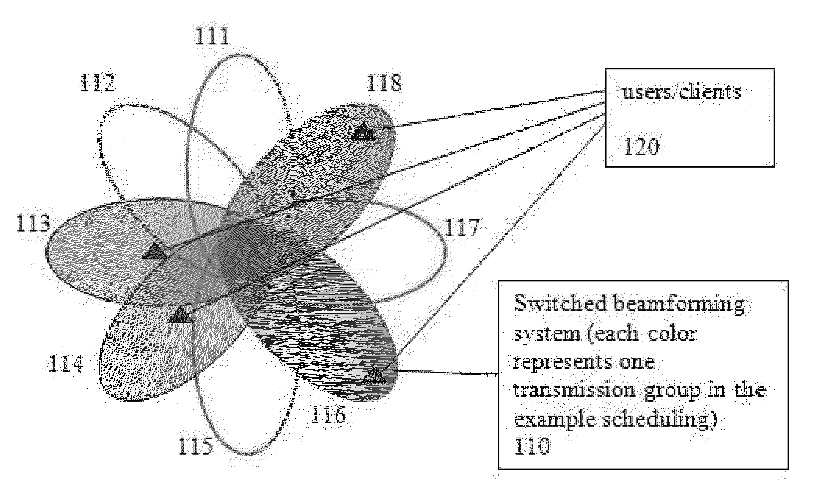
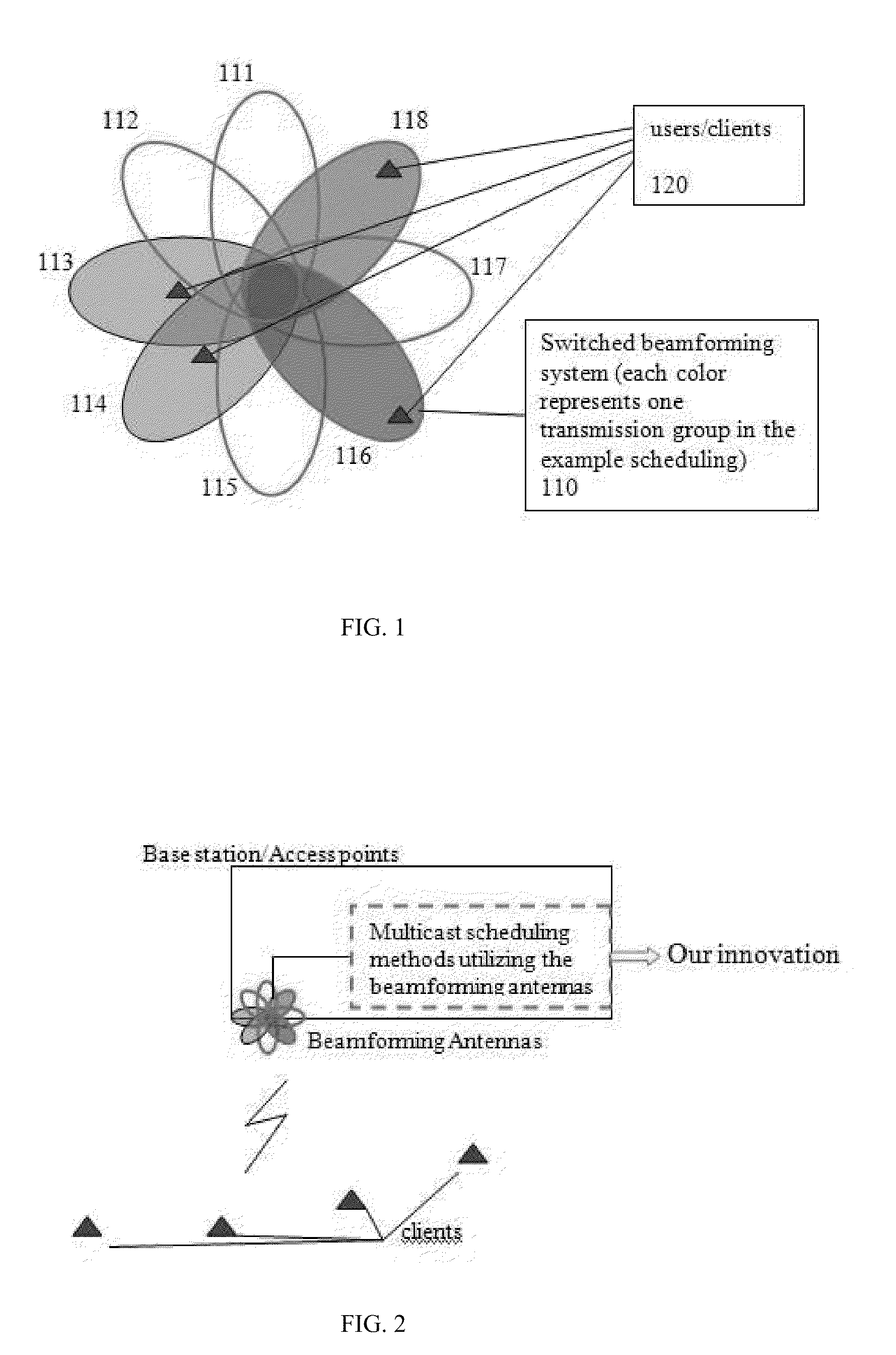
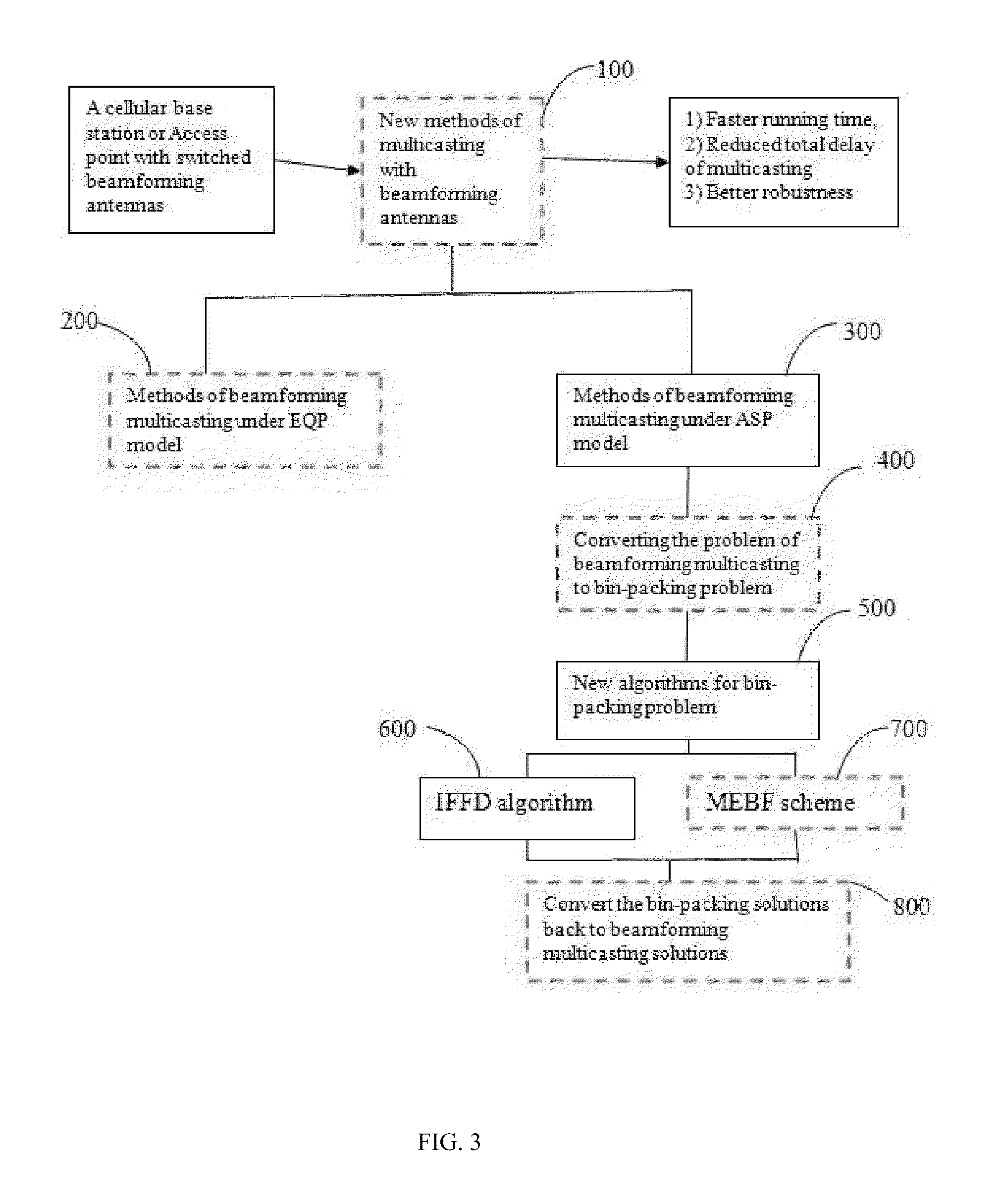
[0018]The invention is directed to the problem of wireless multicasting with switched beamforming antennas, 100 in FIG. 3. In order to exploit both the wireless broadcast advantage and beamforming technologies, the invention divides the single-lobe beam patterns into one or multiple groups and lets each composite pattern comprise a group's single-lobe beam patterns. Then, the same data is transmitted to each composite pattern sequentially. The major issue of how to divide the single-lobe beam patterns into groups, and how to determine the weight / power of each single-lobe beam pattern in a composite one is addressed as follows: Under the EQP (equal power partition) model, the invention develops a dynamic-programming based optimal solution and under the ASP (asymmetric power partition) model, the invention converts the problem to a generalized bin-packing problem and then obtains several approximation solutions. The inventive technique leads to 1) reduced transmission time for a given...


PUM


Abstract

A method for wireless multicasting with beamforming includes dividing single lobe beam patterns into groups, each group being a composite beam pattern, the dividing being according to one of an equal power partition configuration and an asymmetric power partition configuration; and transmitting the information with the composite beam pattern.

Description

[0001]This application claims the benefit of U.S. Provisional Application No. 61 / 312,910, entitled “Wireless Multicasting with Switched Beamforming Antennas”, filed on Mar. 11, 2010, U.S. Provisional Application No. 61 / 450,901, entitled “SVC-Based Multicast Streaming with Beamforming Antennas”, filed Mar. 9, 2011, and this application is related to U.S. patent application Ser. No. ______, entitled “Scalable Video Multicast with Non-Overlapping Beamforming Antennas”, filed Mar. 11, 2011, all of which whose contents are incorporated by reference herein.FIELD OF THE INVENTION[0002]The present invention relates generally to wireless communications, and more particularly, to wireless multicasting with beamforming antennas.BACKGROUND OF THE INVENTION[0003]Wireless multicast / broadcast is becoming increasingly important for efficient dissemination of streaming video as well as common data because the shared nature of wireless medium provides a natural support of wireless multicast and broad...

Claims


Application Information

Patent Timeline
IPC IPC(8): H01Q3/00
CPCH04B7/0617H04B7/0408
Inventor ZHANG, HONGHAIJIANG, YUANXISUNDARESAN, KARTHIKEYANRANGARAJAN, SAMPATH
Owner NEC CORP
Learn More