
Charging system and charging method thereof

a charging system and charging method technology, applied in the field of charging systems, can solve the problems of limited sustainability of batteries for power storage, low market share of power vehicles, and charging usually taking several hours, and achieve the effect of greatly reducing personnel costs

Inactive Publication Date: 2011-11-17
TOPCO SCI
View PDF6 Cites 288 Cited by
  • Summary
  • Abstract
  • Description
  • Claims
  • Application Information

AI Technical Summary

Benefits of technology

[0019](1). The charging system and the charging method can rapidly charge the power of the rechargeable battery through wireless charging so as to enhance the convenience of supplementary power for the electric vehicle.
[0020](2). The charging system and the charging method can rapidly charge the battery through the arrangement and charge through wireless charging. The problems of inconveniently charging at improper locations and long charging time can be solved.
[0022](4). The charging unit of the charging system can be disposed underground. Thus, the charging unit can be directly disposed to a parking lot or a gas station to increase the charging convenience.
[0023](5). The charging system and the charging method do not need to be operated by personals while in the charging mode. The personnel costs can be greatly reduced.

Problems solved by technology

Nowadays, the market share of power vehicles is quite low, and the major problem is that batteries for power storage provide limited sustainability.
Also, the power charging usually takes several hours, which makes the use of power vehicle impracticable.
In another word, the lack of power-charging locations, inconvenience of charging, and the non-commercialized charging mode are the major barriers preventing the development of the power vehicles.

Method used


Image

  • Charging system and charging method thereof
  • Charging system and charging method thereof
  • Charging system and charging method thereof

Examples


Embodiment Construction

[0027]The foregoing and other technical characteristics of the present invention will become apparent with the detailed description of the preferred embodiments and the illustration of the related drawings.

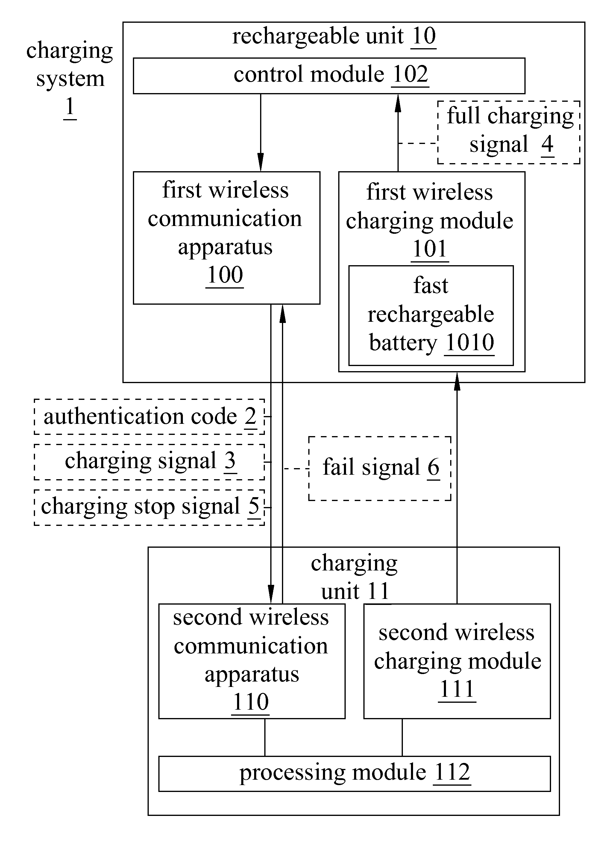
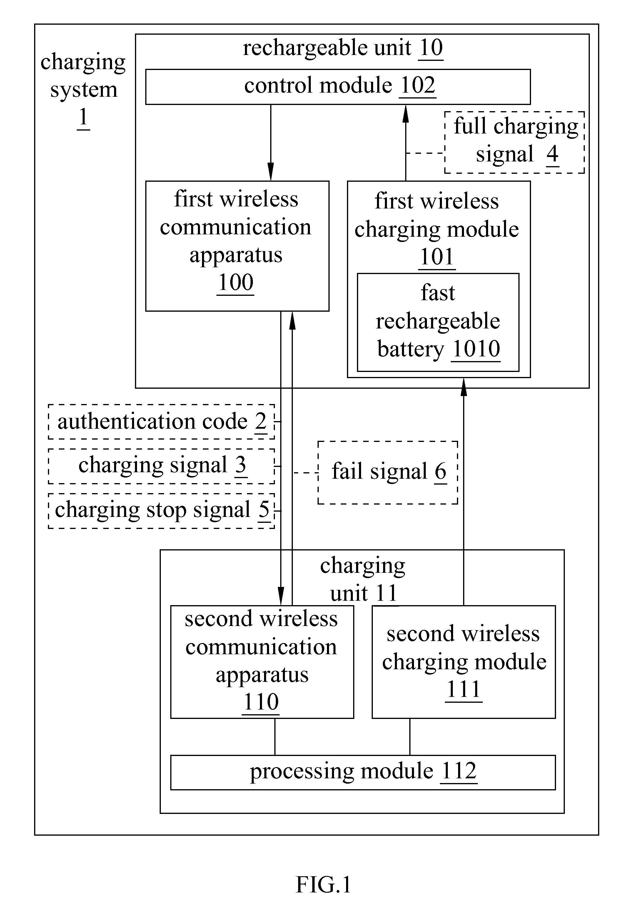
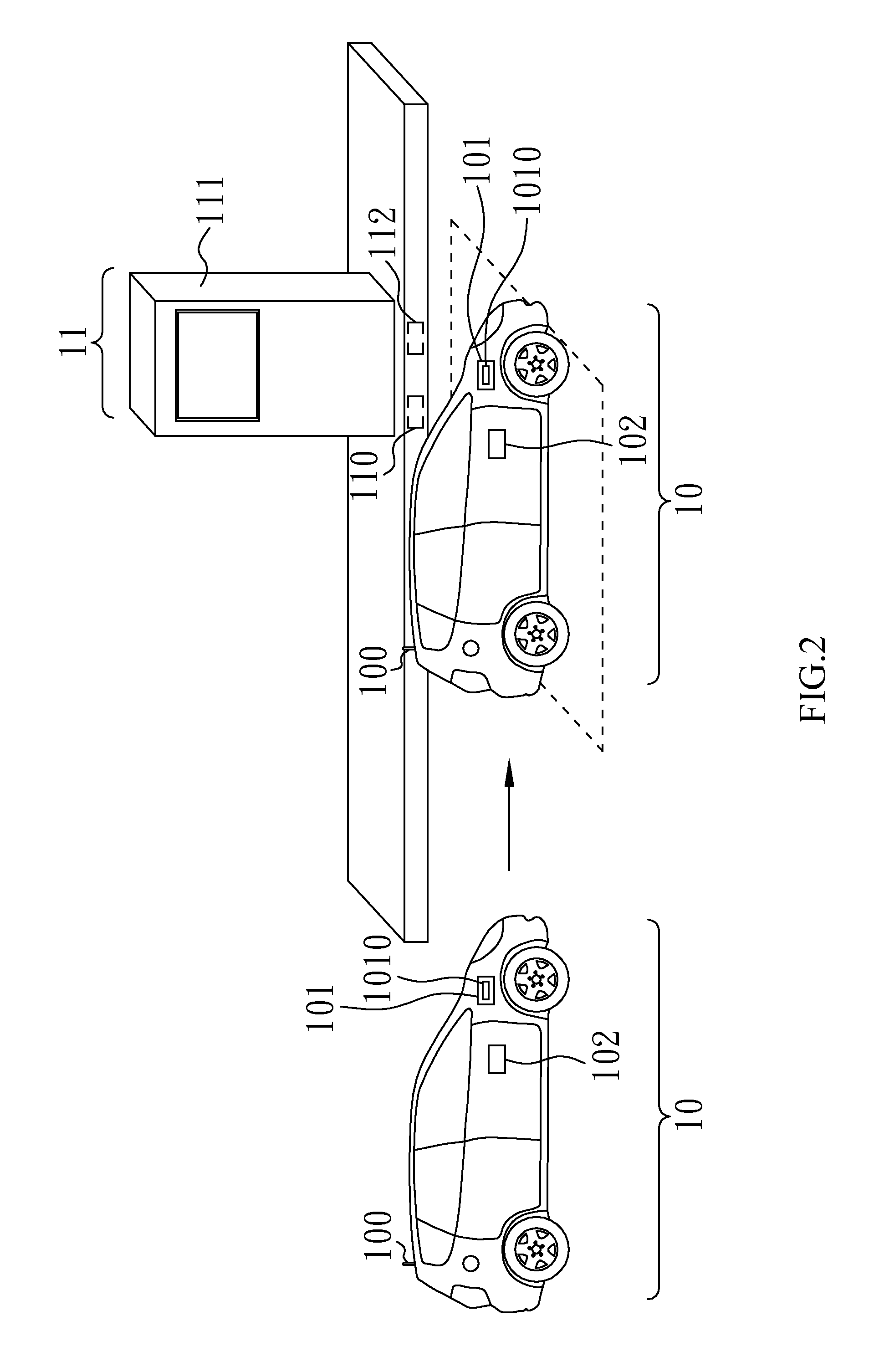
[0028]With reference to FIG. 1 for a block diagram of a charging system in accordance with the present invention is depicted. As shown in the figure, the charging system 1 of the present invention comprises a rechargeable unit 10 and a charging unit 11. The rechargeable unit 10 comprises a first wireless communication apparatus 100 and a first wireless charging module 101. The charging unit 11 comprises a second wireless communication apparatus 110, a second wireless charging module 111 and a processing module 112. The rechargeable unit 10 is power mobile equipment. The power mobile equipment can be an electric vehicle, an electric bus, an electric bicycle, an electric boat, a mobile multimedia entertainment device or a mobile phone. The first wireless communication apparatus 100 ...


PUM


Abstract

A charging system and the charging method are provided. The charging system comprises a charging unit and a rechargeable unit. The rechargeable unit includes a first wireless communication apparatus and a first wireless charging module. The charging unit includes a second wireless communication apparatus, a second wireless charging module and a processing module. The charging method comprises the steps of: transmitting an authentication code and a charging signal to the second wireless communication apparatus by the first wireless communication apparatus; verifying the authentication code by the processing module after receiving the authentication code and the charging signal from the second wireless communication apparatus; charging the first wireless charging module via wireless charging by the second wireless charging module controlled by the processing module when the authentication code is verified.

Description

BACKGROUND OF THE INVENTION[0001]1. Field of the Invention[0002]The present invention relates to a charging system and its charging method, and more particularly to a charging system and the charging method suitable for wirelessly charging a power vehicle.[0003]2. Description of the Related Art[0004]Nowadays, the market share of power vehicles is quite low, and the major problem is that batteries for power storage provide limited sustainability. Comparing to the refueling frequencies of automobiles as one to two times per month, the power vehicle has to be charged every time before driving it. Also, the power charging usually takes several hours, which makes the use of power vehicle impracticable. In addition, the current power charging mode is usually connected to private power sources, rather than commercialized power-charging locations. In another word, the lack of power-charging locations, inconvenience of charging, and the non-commercialized charging mode are the major barriers...

Claims


Application Information

Patent Timeline
IPC IPC(8): G05B19/00
CPCY02T10/7016Y02T90/121B60L11/182B60L11/1846H02J7/025B60L2230/16Y02T10/7088Y02T10/7005Y02T90/16Y02T90/163Y02T90/169Y02T90/14Y02T90/128Y02T90/122Y04S30/14Y02T10/7011B60L53/12B60L53/65B60L53/305H02J50/10H02J50/80H02J7/00045Y02T10/70Y02T10/7072Y02T90/12Y02T90/167H02J50/12H02J50/20
Inventor CHEN, CHIH-HUNGTING, YEN-LING
Owner TOPCO SCI
Learn More