
Method and device for handling of rope

a rope and rope technology, applied in the direction of ropes and cables for vehicles/pulleys, anchor handling/lashing, vessel construction, etc., can solve the problems of substantial load of polyester rope during installation, no solution given for handling ropes, and substantial reduction of the useful capacity of wires

Inactive Publication Date: 2011-11-17
ROLLS ROYCE MARINE
View PDF6 Cites 18 Cited by
  • Summary
  • Abstract
  • Description
  • Claims
  • Application Information

AI Technical Summary

Benefits of technology

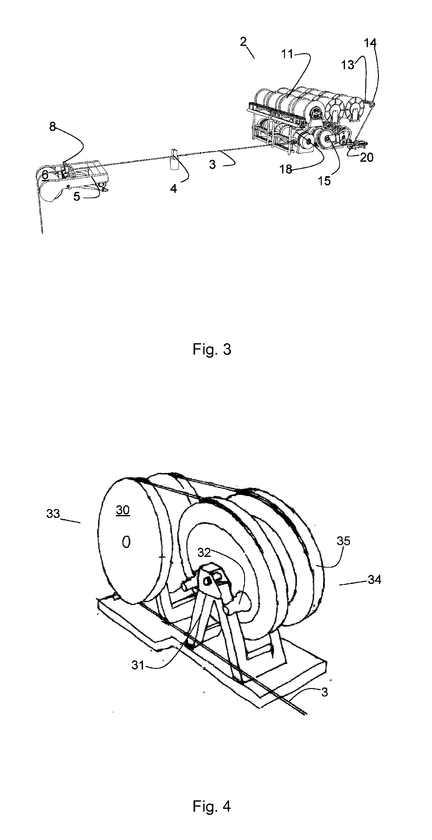
[0009]According to a first aspect, the present invention provides a rope handling system for an offshore vessel for handling of synthetic rope for heavy lifting and deployment operations offshore, the system comprising multiple winch drums adopted for housing a predetermined length of rope, a spooling system to spool in and spool out rope on the drums, a transfer system comprising of sheaves for leading the rope between a drum and a traction winch, the traction winch comprising three or more sheaves, where the sheaves are arranged so that a rope may be arranged from one sheave to the next substantially following a common tangent of the two sheaves and so that the rope rests against about half the circumference of each sheave, and where each sheave operated by an independent motor, and where a rope stopper is arranged downstream of the traction winch relative to the drum upstream of the traction winch. The use of a traction winch having several independently controlled sheaves that will distribute the load over all sheaves, and where the rope follows a track between the sheaves that constitutes a common tangent of two sheaves, will give the advantage that an eye at the end of a rope can be pulled through the traction winch under tension without causing damage to the rope or traction winch.
[0010]According to one embodiment, one or more manipulator(s) is (are) arranged on cranes to allow action of the manipulator(s) at the aft deck of the vessel. Manipulators arranged on cranes at, or adjacent to the deck, allows for remote controlled manipulations at the deck. The remote controlled manipulators allows for remotely controlled permanent connection of the ropes, i.e. without the necessity of having personnel in high risk zones such as the aft deck for this kind of operations.
[0011]According to another embodiment, the rope stopper comprises a rotating member having a substantially vertical axis of rotation, and two substantially vertical pins having a vertical distance greater than the rope to be stopped, arranged at the rotary member. The rope stopper may be designed to be retracted into the deck of the vessel when not in use. This kind of rope stopper gives a rapid and effective locking and unlocking of a rope under tension. The device may be remotely controlled and there is no need for personnel on deck for the operation thereof.
[0018]The method provides for a safe and safe method for substituting one drum for another as source for rope during operations requiring longer ropes than lengths that can be stored on one drum.
[0026]This method provides an effective and safe method for loading rope onboard a vessel, where the rope delivered on a drum or in bulk is brought onboard the vessel and spooled directly onto spools arranged onboard the vessel.

Problems solved by technology

In deep waters the use of wire and chain for anchor handling operations, lifting operations and moorings is prohibited by the weight of steel as the self weight of a long wire or chain will reduce the useful capacity of the wire substantially.
There may be a substantial load in the polyester rope during the installation due to the weight of the anchor and anchor chain suspended at the end of the polyester rope.
A drum is provided for storing of the rope but no solution is given for handling of ropes when the total length of rope exceeds the length that may be stored on one drum.
The '915 patent has no solution for connecting ropes from different drums and for connecting ropes under load conditions, or under high tension.

Method used


Image

  • Method and device for handling of rope
  • Method and device for handling of rope
  • Method and device for handling of rope

Examples


Embodiment Construction

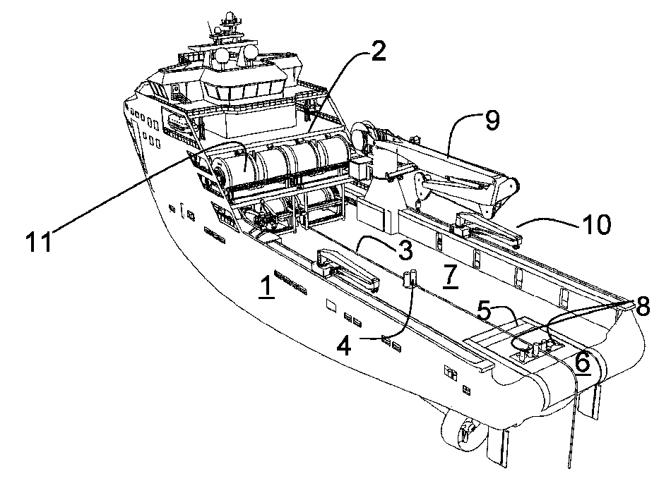
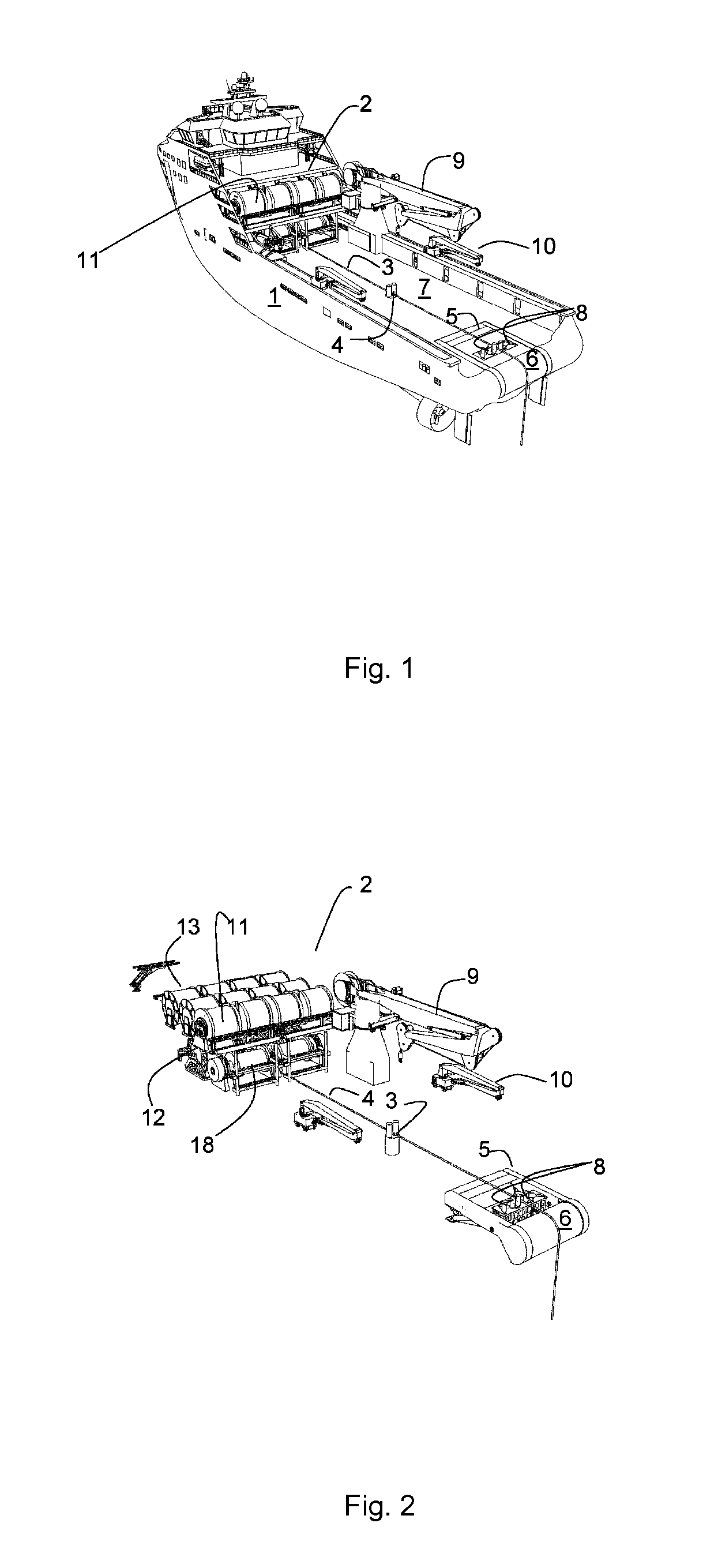
[0036]FIG. 1 illustrates is a perspective view seen from the aft port side of an anchor handling vessel 1, seen from port side and astern, the vessel 1 including a rope handling system 2 according to the present invention.

[0037]A rope 3 is runs over the working deck 7, from the rope handling system 2 via a rope stopper 4 over a stern roller 6 and into the sea. An anchor handling frame 5 is illustrated at the aft end of the deck 7. The anchor handling device is preferably an anchor handling device according to WO 2009 / 005367 A (ODIM ASA) 5 Jul. 2009, which is included herein by reference in its entirety. The anchor handling device may be used for the handling of anchors, e.g. traditional anchors and torpedo anchors, and other heavy loads that is to be either brought onboard the vessel or to be brought from the deck and into the sea. In FIG. 1, the anchor handling frame 5 is illustrated in a resting position where it is arranged in recesses in the deck 7 to leave flat working space.

[0...


PUM

PropertyMeasurementUnit
lengthaaaaaaaaaa
circumferenceaaaaaaaaaa
vertical distanceaaaaaaaaaa

Abstract

A rope handling system for an offshore vessel for handling of synthetic rope (3) for heavy lifting and deployment operations offshore, the system comprising multiple winch drums (11) adopted for housing a predetermined length of rope (3), a spooling system (13, 17) to spool in and spool out rope on the drums (11), a transfer system comprising of sheaves (14, 21, 22) for leading the rope (3) between a drum (11) and a traction winch (15), the traction winch (15) comprising three or more sheaves (30), where the sheaves are arranged so that rope may be arranged from one sheave to the next substantially following a common tangent of the two sheaves and so that the rope rests against about half the circumference of each sheave, and where each sheave operated by an independent motor (32), and where a rope stopper (4) is arranged downstream of the traction winch relative to the drum (11) upstream of the traction winch, is described. A method for handling rope during heavy lifting and deployment operations, and a method for loading rope onto the system are also described.

Description

TECHNICAL FIELD[0001]The present invention relates to the field of anchor handling in offshore operations. More specifically, the invention relates to improvements in rope handling for pre-set of mooring lines, anchor handling and the like, and to equipment for rope handling onboard an anchor handling vessel.BACKGROUND ART[0002]The use of fibre rope is of increasing importance as offshore operations are performed at deeper water depths. In deep waters the use of wire and chain for anchor handling operations, lifting operations and moorings is prohibited by the weight of steel as the self weight of a long wire or chain will reduce the useful capacity of the wire substantially.[0003]When an offshore rig is to be moored in an offshore position especially in deep water or in areas with harsh weather conditions, pre-set moorings are often preferred as it allows the installation of the moorings to be done off the critical path for the rig and the number of days from the rig is in position...

Claims


Application Information

Patent Timeline
Patent Type & Authority Applications(United States)
IPC IPC(8): B66D1/26B66D5/00F16G11/08B66D1/74B63B21/04B66D1/38B23P11/00
CPCB63B21/04B63B21/22B66D1/26Y10T29/49826B66D1/7415B66D5/00B66D1/7405B66D1/74F16G11/08
Inventor INGEBERG, PER
Owner ROLLS ROYCE MARINE
Learn More